
TM 5-3655-210-12
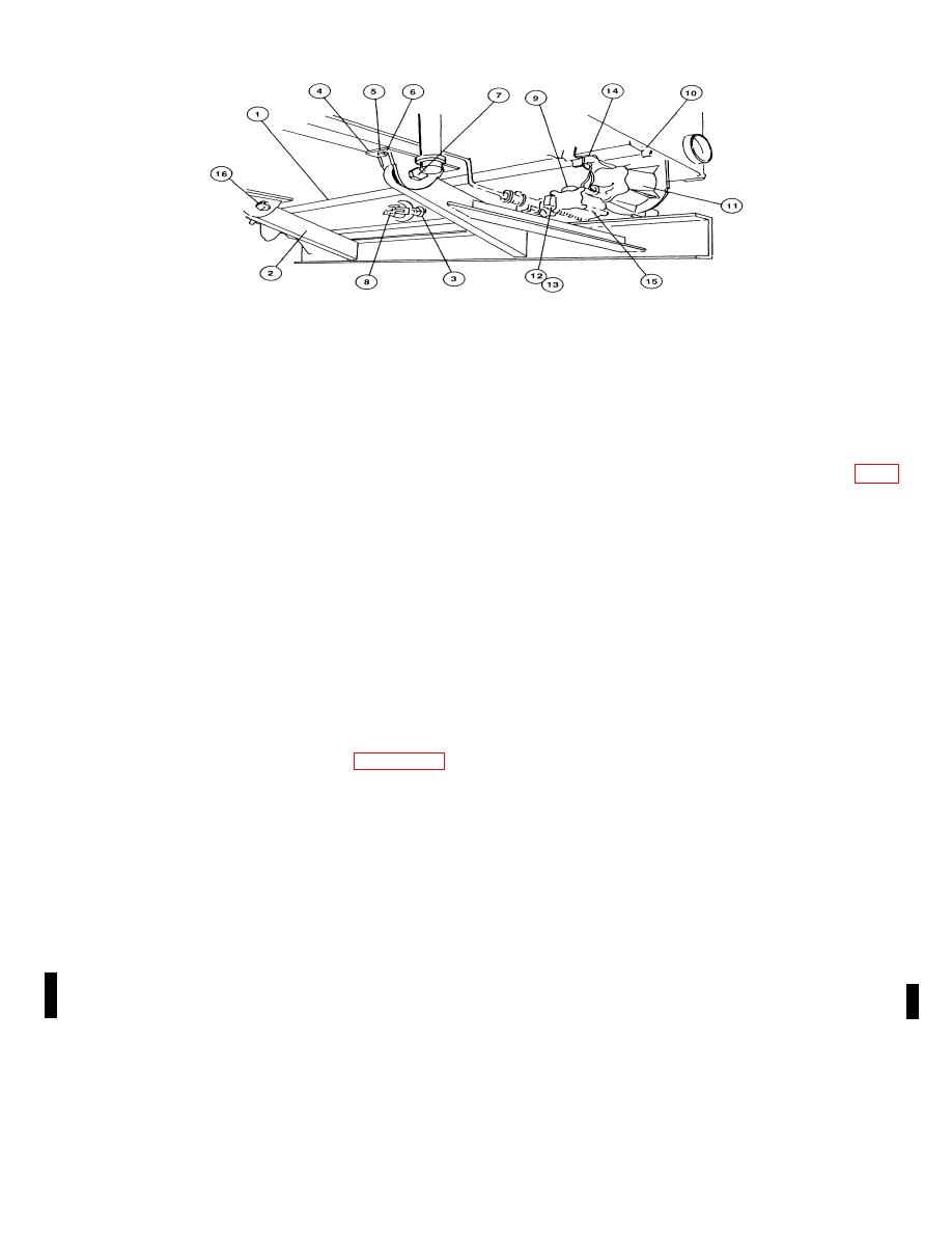
1.
Frame
6.
Capscrew
11.
Service stop and taillight
2.
Bumper assembly
7.
Machine bolt
12.
Capscrew
3.
Nut
8.
Nut
13.
Lockwasher
4.
Bracket
9.
Bracket
14.
Connector
5.
Lockwasher
10.
Bracket
15.
Blackout stop and taillight
16.
Nut
Figure 3-6. Taillight removal.
Clean with a cloth dampened in a cleaning
(1) Place the two batteries (8, fig.
solvent. Inspect for damaged threads, cracked
3-11) in position in the battery holder with the
or broken glass, or any other damage.
negative (-) terminals (1) on each battery
Replace damaged parts. Reverse removal
nearest the rear of the unit.
procedure to reinstall.
(3) Replacing. To replace a burned
(2) Place the two holddown bars (9)
out lamp, unscrew the lens from the front of the
in position on the holddown rods (10) and
light, replace the lamp and screw the lens back
secure with the four flatwashers (11) and nuts
in place.
(12).
3-16. Batteries
(3) Position the connector lead (4)
a. Removal.
with one end on the positive (+) terminal (5) of
one battery and the other end on the negative
terminal (1) of the other battery.
(1) Remove the band (4, fig. 3-10)
holding the boxes (3) together.
(4) Place the ground lead (2) on
the negative terminal (1) nearest the side wall
(2) Remove the boxes from the
and the solenoid lead cable (7) on the positive
storage compartment. Open the boxes and lift
terminal (5) of the other battery.
out the batteries and electrolyte containers.
b. Installation.
(5) Secure the cables to the four
terminals with the four nuts (6).
NOTE
NOTE
Do not mix military batteries and
Use an electrolyte with a specific gravity
maintenance-free batteries.
Under
of 1.280. Do not use tropical electrolyte,
charge or over charge will result.
which will reduce battery reserve
capacity.
(6) Remove the twelve cell caps
from the batteries and add the electrolyte to
each of the cells.
Change 1 3-10
