
TM 5-3655-210-12
1.
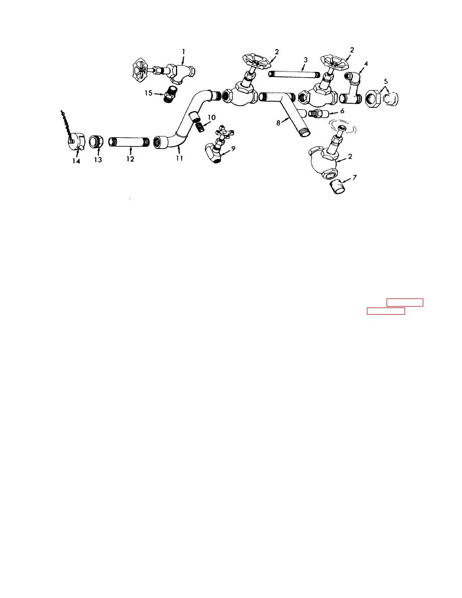
Valve
6. Relief valve
11.
Elbow assembly adapter
2.
Valve (3)
7. Nipple
12.
Nipple
3.
Nipple
8. Tee assembly
13.
1/3 union
4.
Elbow, and tee assembly
9. Valve
14.
Cap
5.
2/3 union
10. Nipple
15.
Adapter
Figure 4-94. CO2 vapor manifold, exploded view.
4-99. CO2 Liquid Level Gases
(12) Unscrew the pipe (12) from the cylinder
filling manifold and lift the manifold from the assembly.
a. Removal.
b. Disassembly.
Refer to figure 4-96' and
(1) Close the valves (3, 4, 15, 16, fig. 4-97).
disassemble the manifold.
(2) Loosen the hose nut (4, fig. 4-98) slightly
WARNING
to relieve the pressure, then loosen entirely, and remove
Dry cleaning solvent, P-D-680 or P-S-
the hose (3).
661, used to clean parts is potentially
(3) Unscrew the tube nut (10) securing the
dangerous
to
personnel
and
tube (11 or 21) depending on which gage is being
property. Use in a well-ventilated
removed.
(4) Remove the adapter (9), elbow (15),
area as the fumes are dangerous if
bushing (14), and nipple (13) from the gage.
inhaled.
Avoid repeated and
(5) Remove the four machine screws(12)
prolonged skin contact. Do not use
securing the gage to the panel, and remove the gage.
near open flame or excessive heat.
WARNING
Flash point of solvent is 100F.-138F.
Dry cleaning solvent, P-D-680 or P-S-
(38C.-59C.).
661, used to clean parts is potentially
c. Cleaning, Inspection and Repair. Wash all parts
dangerous
to
personnel
and
in a cleaning solvent. Inspect the valves, frangible disc
property. Use in a well-ventilated
gage, and washer for any type of damage and replace if
area as the fumes are dangerous if
necessary. Inspect the welds for breaks or cracks and
inhaled.
Avoid repeated and
repair if necessary. Replace all fittings which have
prolonged skin contact. Do not use
damaged threads.
near open flame or excessive heat.
d. Reassembly.
Refer to figure 4-96, and
Flash point of solvent is 100F.-138F.
reassemble the manifold.
(38C.-59C.).
4-106
