
TM 5-3655-210-12
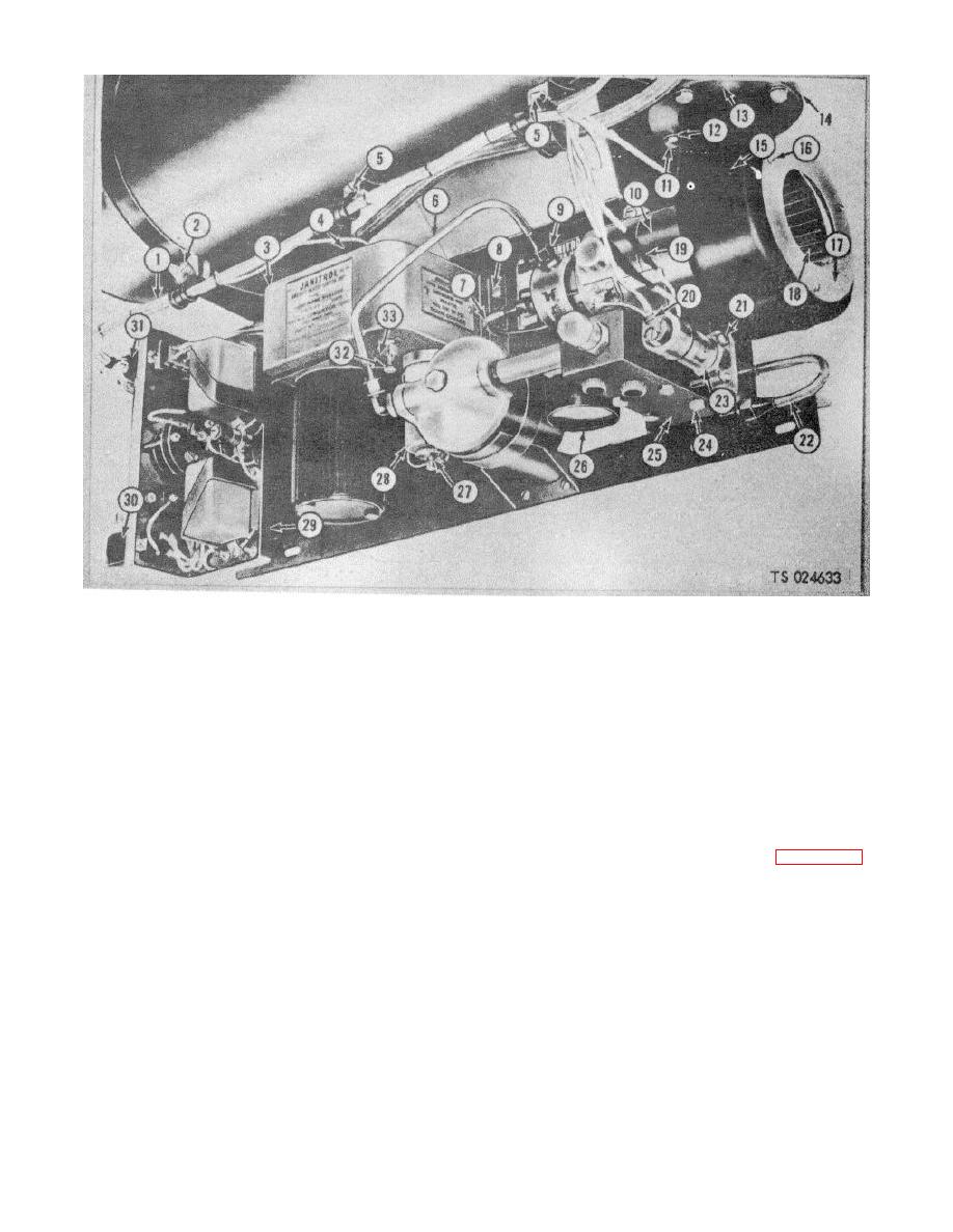
1. Wiring harness
12.
Lockwasher
23.
Solenoid valve
2. Capscrew
13.
Plate
24.
Capscrew
3. Ignition unit
14.
Gasket
25.
Fuel manifold
4. APk plug cable
15.
Blower
26.
Fuel g
5. Machine screw
16.
Self-tapping screw
27.
Thumb screw
6. Fuel tube
17.
Plate
28.
Vibrator
7. Fuel tube
18.
Blower wheel
29.
Control box
8. Machine screw
19.
Taped lead
30.
Disconnect plug
9. Tube nut
20.
Screw
31.
Disconnect plug
10. Fuel pump
21.
Screw
32.
Switch
11. Capscrew
22.
Fuel tube
33.
Lockwire
Figure 4-106. Blower and fuel pump removal
d. Cleaning, Inspection and Repair. Clean the
limits, remove the adjusting screw (4, fig. 4-110) and
the pressure relief stud (6). Reinstall .the adjusting
upper (magnetic) part of the solenoid valve with a cloth
screw without the stud so that it plugs the opening and
dampened in a cleaning solvent. Wash all other parts in
then operate the pump to flush the valve seat. Clean
a solvent. Replace any part with damaged threads.
and reinstall the stud and adjusting screw in the correct
Replace a damaged valve or spring. Inspect the
position.
solenoid valve and the pressure gage for any damage
(2) Adjust the fuel pressure to 30 psi (2.109 kg.
and replace if damaged.
e. Manifold Fuel Filter, Solenoid, Reassembly and
per sq cm) by loosening the locknut (3) and turning the
Installation. Reverse the procedure in a. b. and c.
screw (4).
(3) Check the bypass flow by removing the
above.
fuel line nearest the solenoid valve.
f. Adjustment and Testing.
(4) If the pressure cannot be raised to 30 psi
(1) Check the fuel pressure gage with the
(2.109 kg per sq cm), and there is a good bypass flow,
heater in operation. It should read 30 + 3 psi (2.109 +
replace pressure relief stud.
.2109 kg per sq cm). If the pressure is outside these
4-120
