
TM 5-6640-212-14
(2) Weekly. Check meter readings, and adjust
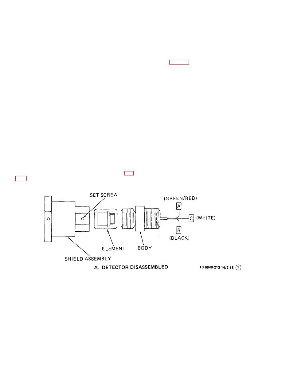
(a) Turn instrument power off.
zeros if necessary while detectors are in a combustible
(b) Loosen the setscrew holding the shield
gas-free environment.
assembly to the body, and unscrew the shield assembly
(3) Periodic. Check response of the instrument
from the body.
periodically by exposing the detector to a sample of
(c) Remove the detector element.
combustible gas of known concentration.
(d) Insert the test socket adapter (23-4027) into
d. Services.
the body (fig. 2-19), and insert the detector element into
(1) Replace pilot, alarms, and fail lights when
the test socket adapter.
necessary.
(e) Using a direct current voltmeter (0-10 volt
(2) Calibrate the instrument, when necessary, as
range), clip the voltmeter leads to terminals A (+) and
follows:
R (-).
(a) Expose the detector to a known concentration
(f) Turn the instrument power on and adjust the
of combustible gas in the air.
detector voltage, using the voltage adjuster on the
printed circuit board. The detector voltage must be 5.5
(b) Correct meter reading by adjusting the gain
vdc. Clockwise rotation increases voltage.
adjuster on the printed circuit board using a known
(g) Turn the instrument power off and remove
concentration of gas or the test and calibration kit, which
the test socket adapter.
can be obtained commercially.
(3) Replace the detector element (e. (2) below)
(h) Insert detector element into the body and
reassemble the detector. Tighten all parts securely, and
whenever it is no longer possible to make the zero
turn the power on.
adjustments within the span of the zero adjuster on the
(2) Element replacement. To replace the detector
corresponding control module. Check detector voltage
element, follow procedures in (1), (a), (b), (c) and (h)
between the detector voltage test points on the printed
circuit board each time the element is replaced.
above.
e. Detector Voltage Measurement and Element
f. Fail Indications. A fail relay and fail light are
Replacement
provided to monitor equipment operations. If equipment
failure occurs, the blue fail light comes on; external
(1) Voltage measurement.
Two people are
failure terminals, switch and alarm circuits are disabled
required to perform the initial detector voltage settings
to prevent false alarms. Fail indications may be caused
and measurements, one person at the control unit (fig.
by:
(1) A short or open circuit in the detector circuit.
18). Refer to figure 2-18 and proceed as follows:
Figure 2-18. Alarm System Detector and Control Unit Disassembled (Sheet 1 of 2)
2-34
