
MWO 9-2330-390-25-1
APPENDIX C:
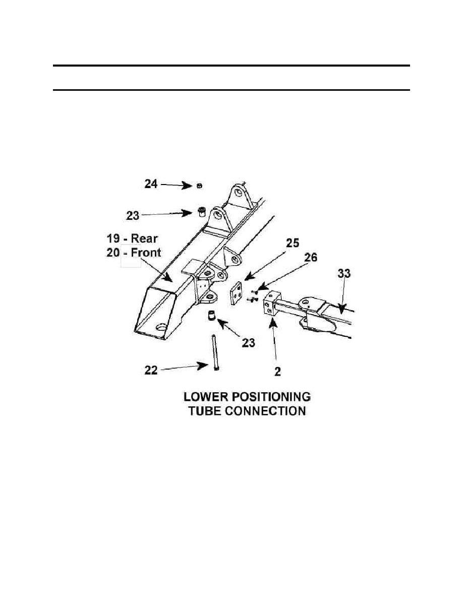
TOP AND BOTTOM BEAM AND HYDRAULIC LIFT
CYLINDER REMOVAL / INSTALLATION (Con't).
NOTE
Ensure that openings for hydraulic fittings in positioning cylinders are aligned
with holes in bottom.
To ensure proper assembly, install items (22), (23), (24) as illustrated below.
7. Insert the positioning cylinder (2) into the lower vertical tube (33) with the hydraulic
connections facing outboard.
8. Insert bolt (22) through one steel bushing (23) with bushing shoulder adjacent to bolt
head. The bolt and bushing sub-assembly should insert through the tube mounting tabs
on the bottom beam, the lower vertical tube (34) and the positioning cylinder base (2).
9. After insertion, place a second steel bushing (23) onto bolt (22). Finish the lower tube
connection by placing locking nut (24) onto bolt (22). Prior to the application of torque,
insure that each of the steel bushings (23) fit into the holes in each tab of the tube mount.
10. Torque lower tube connection bolts (22) to 25-30 ft-lbs.
11. Repeat steps 5 though 10 to complete second lower tube connection.
C-6
