
MWO 9-2330-390-35-1
APPENDIX C:
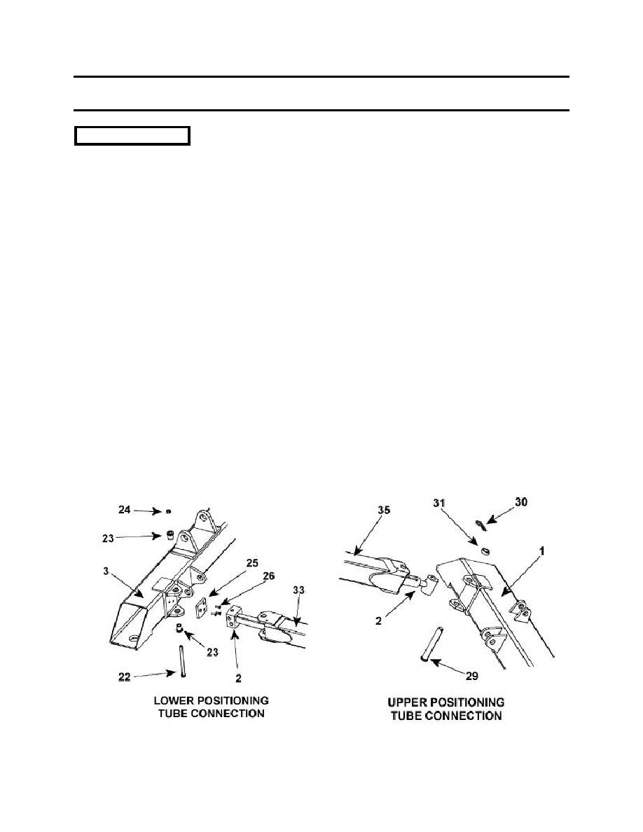
TOP AND BOTTOM BEAM AND HYDRAULIC LIFT
CYLINDER REMOVAL / INSTALLATION (Con't).
c. INSTALLATION
NOTE
Ensure that hole at rod end positioning cylinder is aligned with hole in top beam.
To ensure proper assembly install items (29), (30), (31) as illustrated below.
Ensure that openings for fittings in positioning cylinders are aligned with holes in
bottom.
To ensure proper assembly install items (22), (23), (24) as illustrated below.
1. Install two fully collapsed positioning cylinders (2) inside telescoping vertical tube
(33 &35).
2. Install two clevis pins (29), spacer (31), and new cotter pins (30) on positioning cylinders
(2) and top beam (1).
3. Mount spacer plates (25) to bottom beam (3) using flat head screws (26).
4. With top and bottom beams (1 and 3) fully supported, install two positioning cylinders
(2) on bottom beam (3).
5. Install two bolts (22), bushings (23), and new locknuts (24) on positioning cylinders (2)
and bottom beam (3).
C-6
