
TM 5-6640-212-14
storage for spare ASTM fuel cans. The left (roadside)
d. Main Control Panel. The main control panel (fig.
compartment provides space for a garden hose,
tarpaulin, van grounding rod, and the power entry cable.
compartment. It contains circuit breakers for control of
A toolbox is also mounted on the undercarriage at the
the laboratory equipment.
Instruments and gages
left (roadside).
necessary for surveillance of systems operating
conditions are also provided.
e. Light Switches. Light switches for the electrical
system are shown in figure 1-5. A microswitch for the
blackout lights is located in each of the three outside
doorjambs. Two override switches are provided to
bypass the blackout lights. Eight three-way switches are
located in the van interior, four in the laboratory
compartment and four in the rear compartment. A one-
way switch is located inside the utility compartment.
f. Fume Hood and Gum Bath Controls. The fume
hood and gum bath controls are also shown in figure 1-5.
The switchplate for these controls is mounted on the left
interior laboratory wall immediately above the countertop
access to the centrifuge. There are toggle switches for
the gum bath blower, the fume hood blower, and the van
purging blower.
g. Receptacles. Eight dual receptacles (utility
outlets) are located in the van interior, four in the
laboratory compartment and two each in the rear and
utility compartment. A telephone inlet jack is located
toward the rear of the laboratory compartment roadside
wall.
Motor Starter-Relay Boxes.
The air
h.
compressor, vacuum pump, and water pump motors are
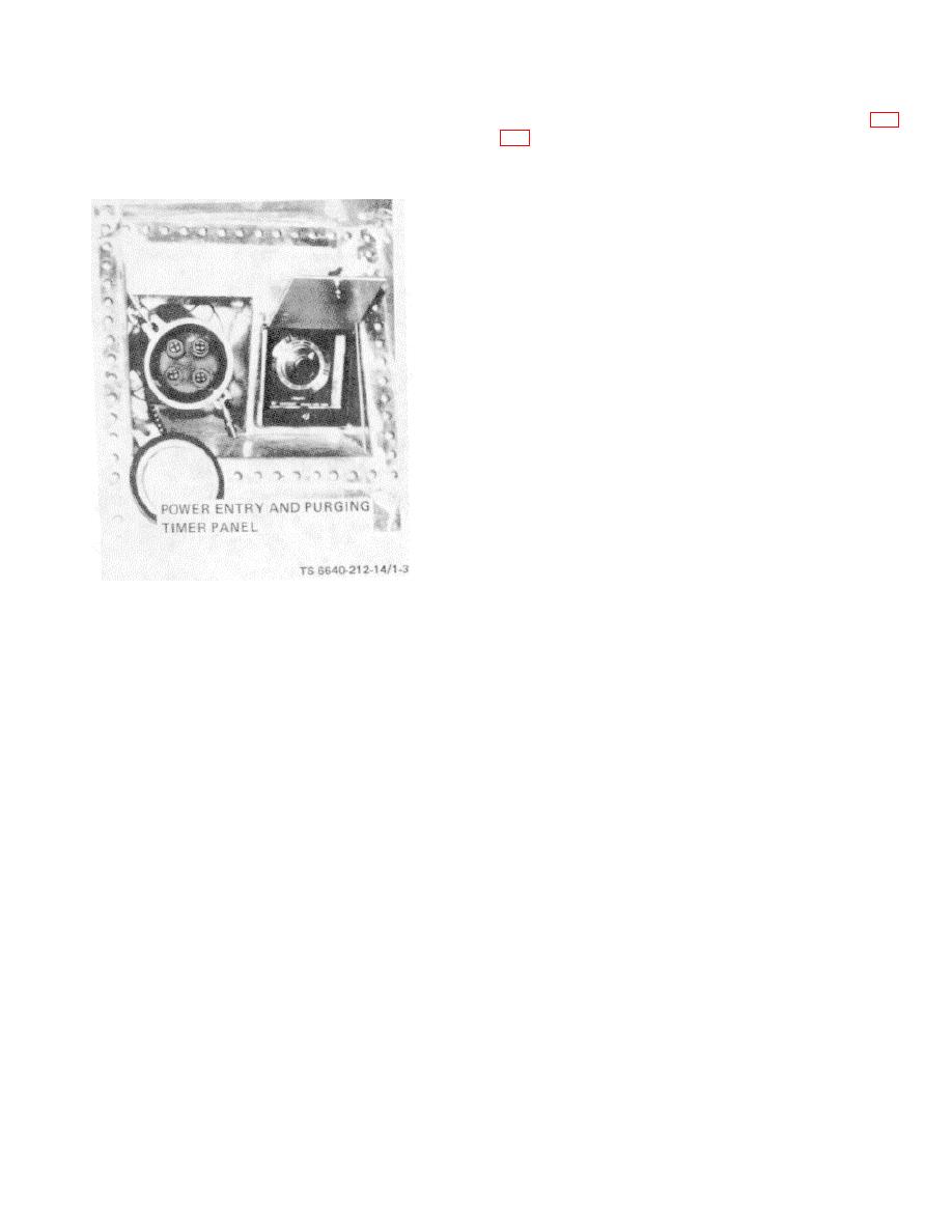
Figure 1-3. Power Entry and Purging Timer Panel
provided with starter-relay boxes located near the
equipment in the utility compartment.
1-7. Electrical System.
i. Interior Lights. Interior lights for the laboratory
are shown in figure 1-6.
a. 110/220-Volt System. The petroleum van is
(1) Fluorescent light fixtures. Six dual 80-watt,
equipped with a 110-volt and a 220-volt electrical
110-watt, fluorescent lights are installed in the interior of
system. The 110-volt system (FO-1, located at back of
the van, four in the laboratory compartment and two in
manual) provides power for interior lighting and
the rear compartment.
laboratory equipment requiring 110 volts. The 220-volt
(2) Incandescent light fixtures.
Four
system (FO-2, located at back of manual) is used for the
incandescent light fixtures are installed in the utility
air conditioning, heating system, and laboratory
compartment. The two rear fixtures each contain a
equipment requiring 220 volts. A power entry receptacle
single, white, 75-watt, 110-volt, heavy duty bulb. The two
and timeclock for purging the van are located on the
front fixtures each contain a white, 75-watt, 110- volt,
rear, left exterior of the van.
heavy duty bulb and a red, 15-watt, blackout bulb.
b. 12/24-Volt System. The van has a 24-volt
(3) Vaportight light fixtures. Two vaportight light
electrical system, but can be connected to a towing
fixtures are installed in the van, one in the fume hood
vehicle with a 12-volt system by using the 12-volt cable
and one in the gum bath area. Each fixture is equipped
adapter (stored in toolbox) furnished as a basic issue
with a 75-watt, 110- volt, ruggedized bulb.
item. Before the van is connected to the 12-volt system,
the 24-volt lamps in the tail light, brakelight and
clearance lights, must be replaced with 12-volt bulbs.
c. Master Switchboxes. Two master switchboxes
are located in the rear compartment. The switchboxes
control the 110-volt and 220-volt circuits.
Each
switchbox is provided with a circuit breaker.
1-5
