TM 5-6640-212-14
NOTE
(b) Hold setting knob so it does not turn while
making adjustment. After making adjustment move the
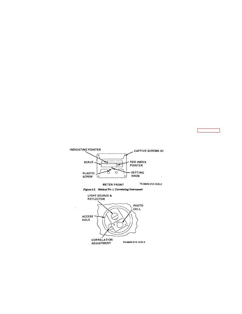
Not making this adjustment will not
red pointer to the indicating pointer to see if control
affect the operation of the instrument
action takes place where they coincide when instrument
since the indicating pointer always
is powered. If they do not, repeat above procedure.
indicates true temperature and set
(5) Method 2, for older instruments.
pointer may be set up or down scale
(a) Loosen the four corner screws on the
to compensate for the difference.
instrument and pull meter forward and out of the
(2) To bring the two pointers in line it is necessary
housing. After blowing off all dust, pry up the plug button
to move the red pointer either to the right or left.
in the top of the meter. Turn the setting knob clockwise
(3) Note how many scale divisions the pointer
until the red pointer is at the top of the scale. The setting
must be moved, and in which direction. It may then be
arm carrying the photocell and light source is then
moved by either one of two methods.
visible.
(4) Method 1, for newer instruments.
(b) Insert a small screwdriver into slot and turn
(a) Remove black plastic screw from the
clockwise or counterclockwise to adjust red pointer the
underside of the front directly under the scale (fig. (5-2).
required distance. Replace plug button and replace
By moving the red pointer near to the hole it can be
meter in housing.
pushed either right or left with the aid of a suitable size
(c) Move red pointer to indicating pointer, with
rod pushed through the hole.
instrument provided, to see if control action takes place
CAUTION
where pointers coincide. If no action takes place repeat
Do not move red pointer far enough
the above procedures. When adjustment has been
to touch scale or pointer will bind.
completed tighten four corner screws.
h. Troubleshooting.
Refer
to
for
troubleshooting procedures.
Figure 5-3. View Through Access Hole
5-5


