
TM 9-2510-247-13&P
0010 00
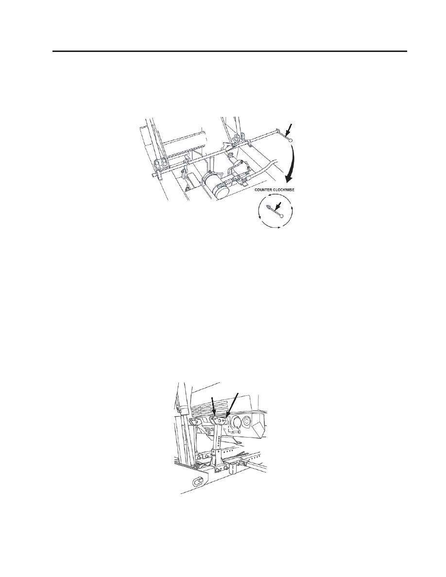
CONNECTING TO TOWED VEHICLE - Continued
5.
Using remote control or valve control levers, BOOM EXTEND until transport leg assemby is
free of fifth wheel. Rotate handle (3) counter-clockwise and raise transport legs.
3
3
Figure 45. Support Leg Assembly
6.
Using remote control or valve control levers, BOOM RETRACT until boom touches ground.
NOTE
If towed vehicle is not equipped with front towing eyes, skip step 6.
7.
Position upper section (4) of towbar assembly under front towing eye (5) of towed vehicle. Adjust tow bar
assembly back as needed.
8.
Using remote control or valve control levers, BOOM RETRACT to lift boom extensions to allow
for ground clearance when attaching 1/2 inch chains.
5
4
Figure 46. Tow Bar Assembly Location
0010 00-3
Change 1
