TM 9--2520--215--34
0005 00--11
THEORY OF OPERATION -- CONTINUED
0005 00
HYDRAULIC SYSTEM – Continued
Action Of Hydraulic System in Reverse Range, Converter Drive, No Steer
NOTE
Refer to Torque path in Reverse Range, Converter Drive, No Steer schematic view and
Hydraulic System, Reverse range--No Steer--schematic view.
In reverse range, the hydraulic system functions as describe in neutral--range operation. The only differences are:
The reverse--range clutch is applied.
The out pressure and brake coolant pumps operate in a reverse direction. The oil passage from the range
selector to the top of the main pressure--regulator valve is exhausted.
When the range--selector valve directs pressure to the reverse--range clutch, lockup cannot occur. Therefore, al-
though the throttle position may actuate the lockup relay valve, the valve will have no function.
The brake coolant pump reverse rotation draws air (or air/oil mixture) from the lines leading to the output reduction
gear assemblies. The air or mixture is discharged at the air valve, which is open when brakes are released. This loss
is negligible.
The output--driven pressure pump reverse rotation recalculates a small portion of the oil pumped by the input--driven
pump.
When the line at the top of the main pressure--regulator valve is exhausted, main pressure is higher, as it is during low
range. The shift inhibitor will prevent a shift to any other range, above certain output speeds. Refer to Downshift In-
hibitor Limits.
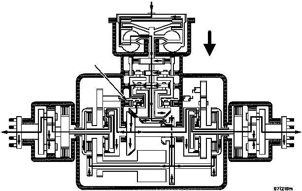
DIRECTION OF TRAVEL
REVERSE---RANGE
CLUTCH APPLIED
Torque Path in Reverse---Range, Converter Drive, No Steer---Schematic View