
TM 9-4940-507-14&P
OPERATION & MAINTENANCE INSTRUCTIONS (Cont.)
screw driver, loosen the Lock nuts 55-876 and 55-811.
back off Lock nut 55-876 one full turn and bring up Lock
CONNECTING AIR LEAK THROUGH GUN OR
nut 55-811 and tighten snugly. Reassemble in reverse
AROUND VALVE STEM: Air leaking through the gun is
order.
caused by the Valve Stem Assembly 55-874 not seating
properly. Air leaking around the Valve Stem may be
When Used With A Cup: A compatible solvent should
caused by worn Packings 55-548 or damaged Valve
be siphoned through gun by inserting tube from siphon
Stem 55-874. Remove Connection 55-885, Spring 55-
cup in an open container of solvent. Trigger gun
826, Stem 55-874, Nut 55-825 and Packing 55-548.
intermittently to thoroughly flush passageways and
Thoroughly clean parts and inspect for damage. Replace
internal parts
worn or damaged parts, put one drop of oil on Packings
55-548 and reassemble in reverse order.
TO ADJUST FLUID NEEDLE WHEN WORN: To adjust
the fluid needle remove Control Screw 55-875, Spring
55-881 and Needle Assembly. With " wrench and a
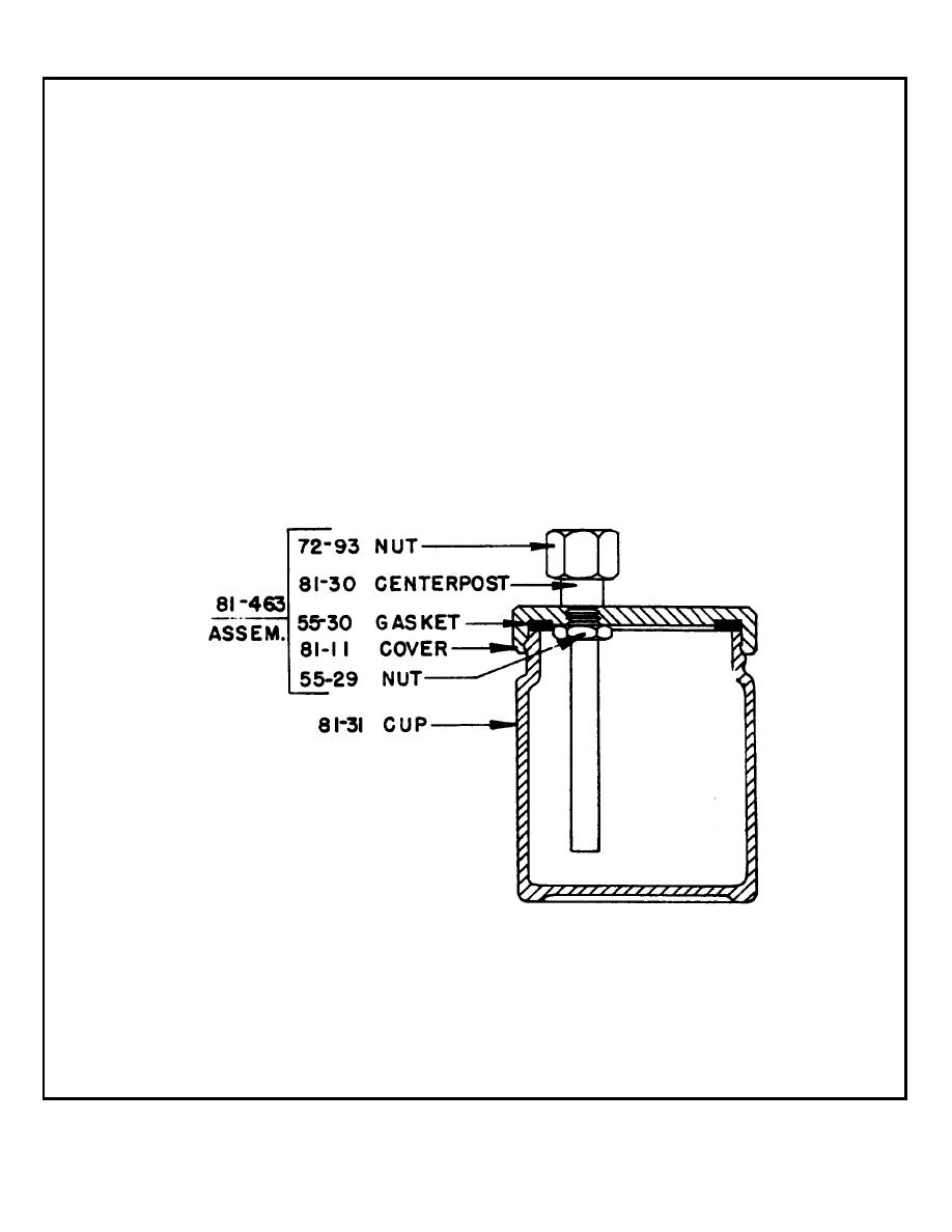
MODEL 81-582 CUP
4 OZ., GLASS SCREW TYPE WITH 1/4 NPS CONNECTION THREAD
PARTS LIST
PART
PART
NO.
DESCRIPTION
QTY.
NO.
DESCRIPTION
OTY.
55-29
NUT ...........................................1
81-30
CENTERPOST ................................... 1
55-30
GASKET ....................................1
81-31
4 OZ. GLASS CUP ............................ 1
72-93
NUT ..........................................1
81-463
CUP COVER ASSY ............................ 1
81-11
COVER......................................1
2
