
TM 5-3655-210-12
1.
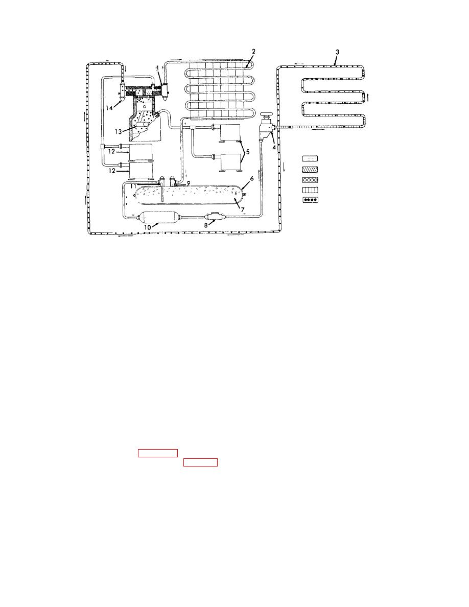
Discharge service valve
8.
Sight glass
2.
9.
Receiver inlet valve
3.
Evaporator coil
10.
4.
Expansion valve
11.
Receiver liquid outlet valve
5.
Suction pressure switch (gas and electric)
12.
Discharge pressure switch (gas and electric)
6.
Receiver
13.
7.
Refrigerant
14.
Suction service valve
Figure 2-7. Refrigeration flow diagram.
smothering to death. Small percentages of C02 will
cause tiredness and perhaps headaches. Three percent
in the air doubles breathing efforts, and five percent
causes panting.
Eight percent will cause marked
distress and ten percent causes unconsciousness very
quickly.
Turn the reversing switch to one of the
ON positions only long enough to observe the rotation of
2-4.
Electric Motor Operation
the shaft. The shaft should rotate counterclockwise when
a. Automatic Operation. Make certain the motor
viewed from the shaft end of the motor. If the shaft
rotates in the proper direction, turn the motor starting
starting switch and the reversing switch are in the OFF
switch to the AUTOMATIC position, and return the
position; and the power line is connected to the trailer
reversing switch to the same ON position. If the shaft
208 VAC-power receptacle (1, fig. 2-11). Disengage
rotates in the wrong direction, turn the motor starting
the three countershaft clutches (1, 2, and 9, fig. 2-3).
switch to the alternate ON position. The position of the
Turn the motor starting switch (fig. 2-9) to the HAND
reversing switch must not be changed unless a power
position.
source of different phase sequence is used. With the
above steps performed, the electric motor will start
whenever the high tank pressures close the tank pressure
switch, which controls the electric motor.
2-8
