
TM 5-3655-210-12
Table 2-1. Valves
Tag
Description
No.
1
Liquid fill line (storage compartment, thru pump)
2
Liquid shut-off (storage)
3
Liquid fill line (by-pass pump)
4
Liquid line shut-off (conversion)
5
Liquid equalizing line
6
Dehydrator by-pass
7
Vapor equalizing line
8
Vapor return (conversion)
9
Vapor return (storage)
10
Transfer pump bleed-off
11
Low pressure gage line (conversion)
12
Liquid shut-off to cylinder fill compressor
13
High pressure vapor return
14
Pressure regulating valve
15
Strainer bleed-off
16
Cylinder valve
17
Cylinder fill hose bleed-off
18
Cylinder valve
19
Cylinder fill hose bleed-off
18
Cylinder valve
19
Cylinder fill hose bleed-off
20
Low pressure gage line (storage)
21
High pressure gage line (conversion)
22
High pressure gage line (storage)
23
Safety vent switching valve (conversion)
24
Safety vent switching valve (storage)
25
Fire valve
26
Transfer hose bleed-off (by-pass pump)
27
Transfer hose bleed-off (thru pump)
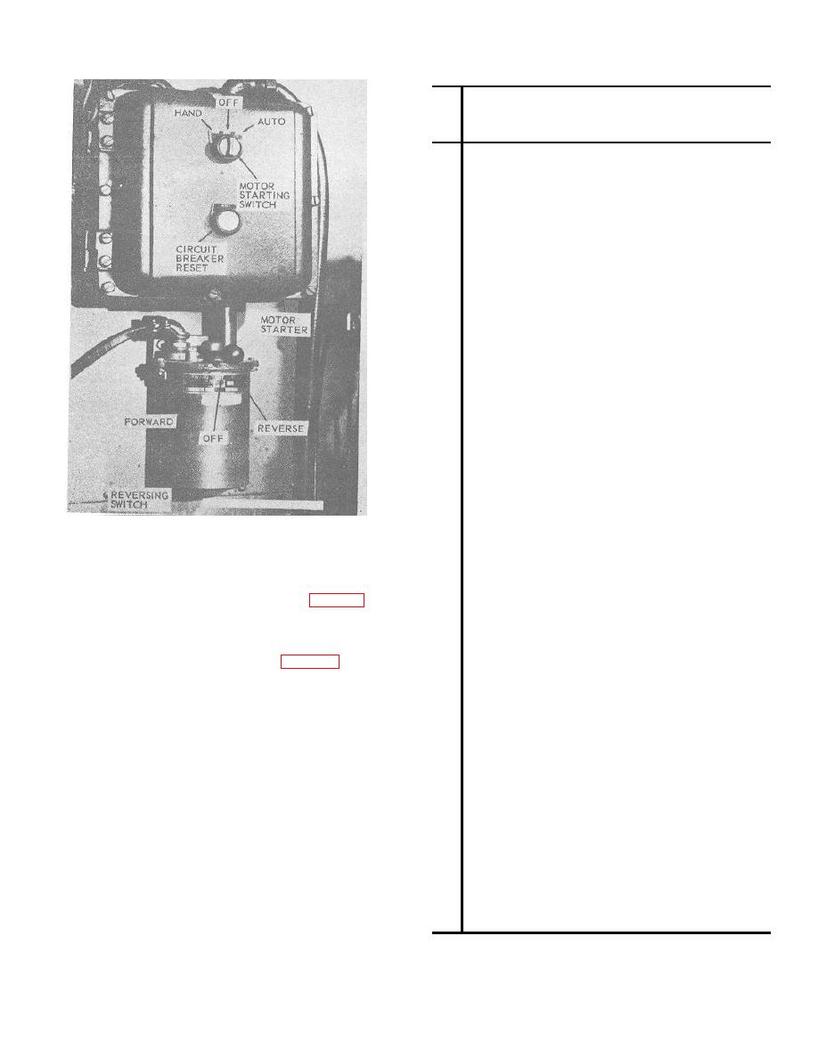
Figure 2-9.
Electric motor starter and reversing
28
Transfer hose bleed-off (vapor)
switch
29
Relief valve--3/4 male (1.905 cm)-341 psi (23.9723
kg per sq cm) (storage)
carburetor by working the priming lever (27, fig. 2-8) up
30
Relief valve-3/4 male (1.905 cm)-341 psi (23.9723kg
and down until the carburetor is full. This is indicated by
per sq cm) (storage)
31
Relief valve--3/4 male (1.905 cm)-341 psi (23.9723
a reduction of pressure on the priming lever. It takes
kg per sq cm) (conversion)
approximately 24 strokes to fill the carburetor. Close
32
Relief valve-3/4 male (1.905 cm)-341 psi (23.9723 kg
the manual-automatic toggle switch (13, fig. 2-2) on the
per sq cm) (conversion)
engine control panel to the AUTOMATIC position. The
33
Bleeder valve-3/8 female (.9525 cm)-330 psi (23.199
gasoline engine will now start when high tank pressures
kg per sq cm) (conversion)
close the circuit to the tank pressure switch.
34
Bleeder valve-3/8 female (.9525 cm)-330 psi (23.199
b. Manual Operation. The tractor-trailer toggle
kg per sq cm) (conversion)
switch (2) on the engine panel should be in the trailer
35
Vapor line relief
position. The circuit breaker (3), mounted on the engine
36
Safety relief (pop type) 375 psi (26.3625 kg per sq
control panel should be ON or in the up position. On
cm) (transfer pump discharge)
serial number units L-1475-T through L-1478-T, prime
37
Safety relief disc-1500 psi (105.45 kg per sq cm)
38
3 way valve (conversion heater coil)
the carburetor (a. above). Hold the gasoline engine
39
3 way valve (compartment heater)
START switch (12) mounted on the engine control panel
40
Expansion valve, refrigeration system
up, until the engine starts, then release the switch. To
41
Air tank bleed-off (brakes)
stop the engine hold the engine STOP switch (11) up
42
Heater fluid pump bleed-off (outlet)
until the engine is completely stopped.
43
Refrigerator compressor suction valve
44
Refrigerator compressor discharge valve
45
Receiver tank shut-off (outlet)
46
Receiver tank shut-off (inlet)
47
Heater fluid pump bleed-off (inlet)
2-10
