Home
Download PDF
Order CD-ROM
Order in Print
Figure 2-12. Refrigeration compressor, installed view.
Figure 2-16. Transfer of liquid from the conversion pressure vessel to the storage pressure vessel.
TM-5-3655-210-12 Conversion Storage and Charging Unit Carbon Dioxide: Gasoline Engine or Electric Motor Driven Manual
Page Navigation
16
17
18
19
20
21
22
23
24
25
26
TM
5-3655-210-12
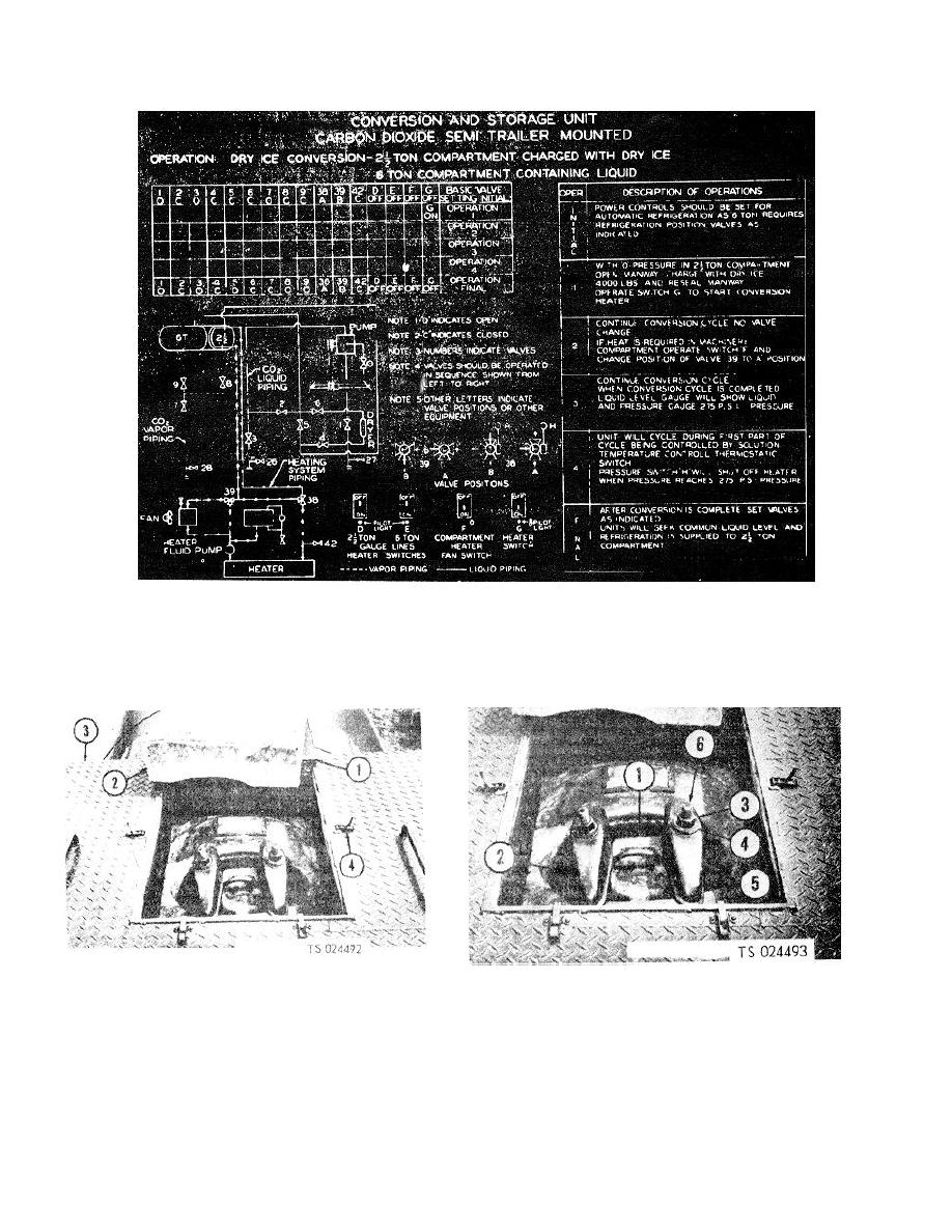
Figure
2-13
.
Normal
conversion
operation
.
1.
Hatch
cover
3.
Platform
1.
Cover
4.
Washer,
flat
2.
Insulation
block
4.
Locks
2.
Gasket
5.
Clamp
3.
Nut
6.
Bolt
Figure
2-14
.
Manway
access
.
Figure
2-15.
Manway
cover
2-14