
TM 5-3655-210-12
h. Set the unit for automatic operation, and engage
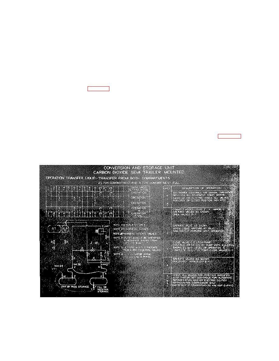
empty, or sufficient liquid has been pumped into the.
receiver unit.
only the refrigeration clutch.
With all the liquid
f. Disengage the clutch to the transfer pump.
contained in the storage pressure vessel, set the valves
Close the liquid fill and vapor equalizing line valves on
in the normal position as indicated in figure 2-13.
the receiver unit.
2-11. Transfer of Liquid Carbon Dioxide from Both
g. Close valves 3, 6, and 7. Open valves 26 and
Pressure Vessels Simultaneously.
28 to bleed off carbon dioxide trapped in the transfer
hoses, and then disconnect the transfer hoses.
h. Set the valves for the normal position as
a. Set the driving unit for manual operation, and
indicated in Figure 2-13. Set the controls for automatic
disengage all clutches.
b. Set the valves as indicated in figure 2-22 and
operation, and engage the refrigeration clutch only if
liquid carbon dioxide is remaining in the pressure
start the driving unit. Refer to table 2-1 for valve
vessels.
identification.
c. Connect the liquid and vapor transfer hoses
2-12.
Transfer Of Liquid Carbon Dioxide From The
(stored in the storage compartment) to the liquid fill line
Storage Pressure Vessel (Liquid In The
and vapor equalizing line at the rear of the trailer, and to
Storage Pressure Vessel Only)
the receiver unit.
d. Close valves 1, 3, 10, 26, and 28 (fig. 2-22).
a. Set the driving unit for manual operation, and
Open the liquid fill and vapor equalizing line valves on
disengage all clutches.
b. Set the valves as indicated in Figure 2-23 and
the receiver unit.
e. Open valves 3, 6, 7, and 10. When liquid
start the driving unit. Refer to Table 2-1 for valve
appears at valve 10, close the valve and engage the
identification.
c. Connect the liquid and vapor transfer hoses
transfer pump clutch. Continue to pump liquid into the
receiver unit until the pressure vessels are
(stored in the storage compartment) to the liquid fill
TS 024500
Figure 2-22 .
Transferring liquid from both compartments .
2-21
