
TM 5-3655-210-12
Section XXIII. CONVERSION HEATER
4-106. Description
pressure gage, solenoid valve, and a fuel manifold. The
heater is operated on 24-volt DC from' the electrical
The conversion heater speeds the process of
system of the vehicle. It is hooked to the heater control
converting solid carbon dioxide into liquid carbon
panel (8, fig. 4-102) by disconnect plug (10). Power is
dioxide in the conversion pressure vessel. The heater is
transmitted through the control panel to the water pump
mounted in the storage compartment (fig. 4-100) and
(9), ignition unit (6), water temperature thermostat (1),
can be operated manually by a toggle switch (9, fig. 4-
water temperature limit switch (2), stack temperature
101) on the DC control panel. The heater is normally
switch (3), and the fuel pump and blower motor (5). The
operated automatically, except when used in
current to the spark plug (7) in turn comes from the
conjunction with the space heater in the power
ignition unit. An expansion tank (4, fig. 4-100) is the
compartment. Heat is produced by burning gasoline
reservoir for the heater fluid.
supplied by a motor driven fuel pump. The fuel system
also contains a fuel filter
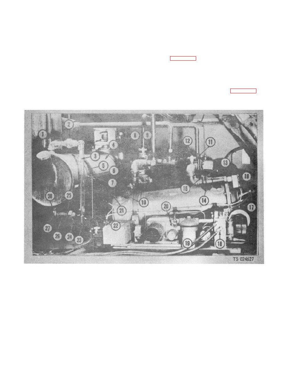
1. Filler cap
2. Union nut
11.
Conversion heater diversion valve
8. Sight glass
12.
Anti-freeze bleed-off petcock,
21.
Heater fluid line
4. Expansion tank
14.
Gasket
22.
Saddle stand
5. Saddle stand clamp
15.
Capscrew
23.
Drain cock
6. Capscrew
16.
Spark plug
24.
1-3 union
7. Nut
17.
Coupling nut
25.
1/3 union
8. Anti-freeze bleed-off petcock
18.
Tube nut
26.
Nipple
9. Compartment heater diversion valve
19.
Fuel pressure gage
27.
Elbow
10. Tube nut
20.
Vibrator switch
28.
Nipple
Figure 4-100. Conversion heater, installed view.
4-113
