MWO 5-2330-360-23-1
10. INSTALLATION PROCEDURE M870A1 BRAKE MOD (BENDIX) (Continued).
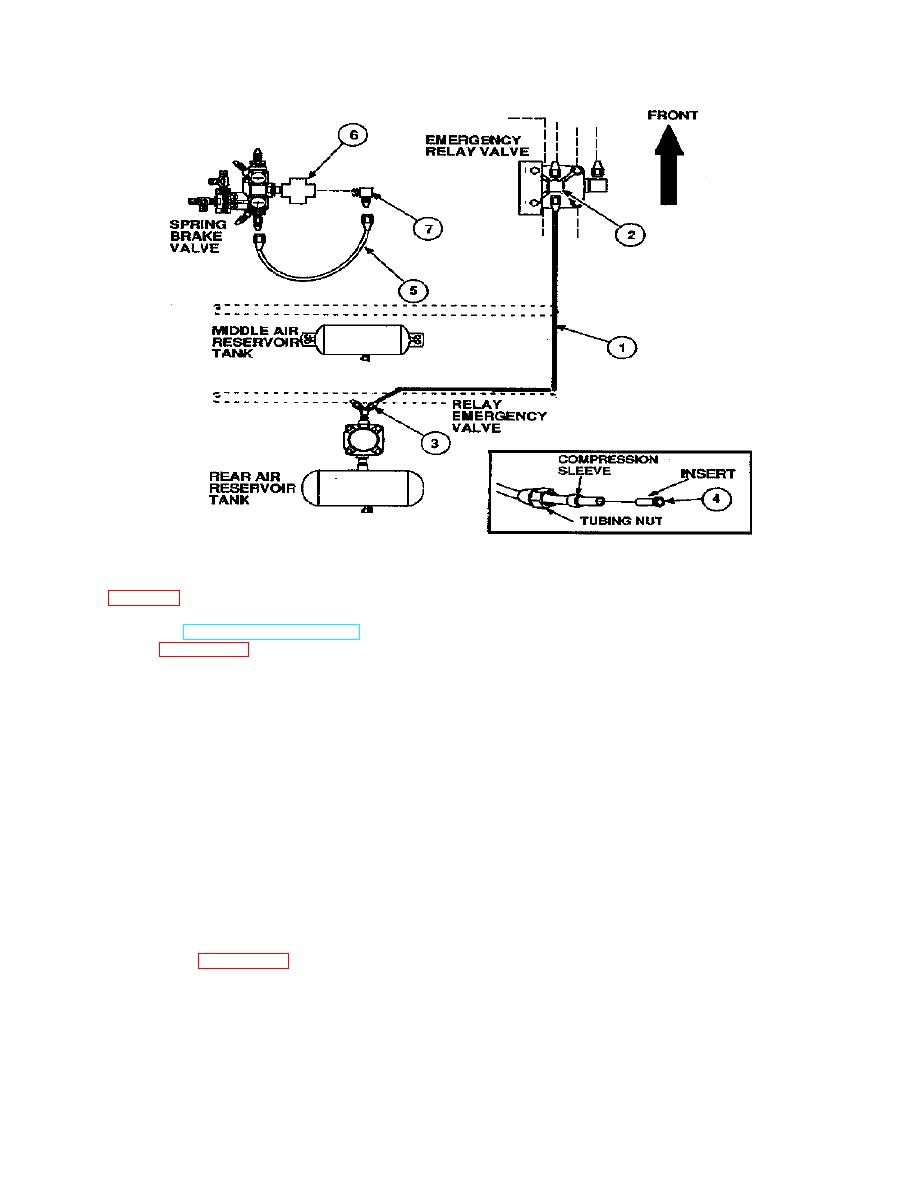
Figure 29.
Refer to Figure 29.
(1) Refer to TM 5-2330-378-14&P. Remove the rear axle brake chamber air hoses. Dispose of hoses in
accordance with paragraph 8d. Turn elbows rearward.
(2) Run a new service line (3/8" tube) (1) from the relay valve top tee (2), rear connection, rearward along the
right main frame rail through the support brackets. Proceed to the rear air reservoir tank relay emergency valve upper 45
degree elbow (3).
(3) Remove tubing nut and sleeve from the relay valve top tee (2), rear connection. Install tubing nut, sleeve, and
tubing insert (4), PN246089, on the relay valve end of the new service air line (3/8"tube) (1). Connect new service air
line to the relay valve, top tee (2), rear connection.
(4) Recheck routing and length of the new service air line (1) to the rear air reservoir tank relay emergency valve.
Mark the length and cut the new service air line at the relay emergency valve location.
(5) Remove tubing nut and sleeve from the relay emergency valve, upper 45 degree elbow (3). install tubing nut,
sleeve. and tubing insert, PN 246089, on the relay emergency valve end of the new service air line (3/8" tube). Connect
new 3/8" service air line (1) to the relay emergency valve, upper 45 degree elbow (3).
(6) Disconnect the short air line 3/8" tube(5) on the large cross fitting (6), right side. Remove elbow (7). Dispose of
elbow as described in paragraph 8d..
(7) Install elbow (removed from relay valve, 1/2-inch pipe to 1/2-inch tube) in the large cross fitting (6) right side,
facing forward.
30


