
TB 5-2520-551-24
SPEED CONTROL GROUP (cont.)
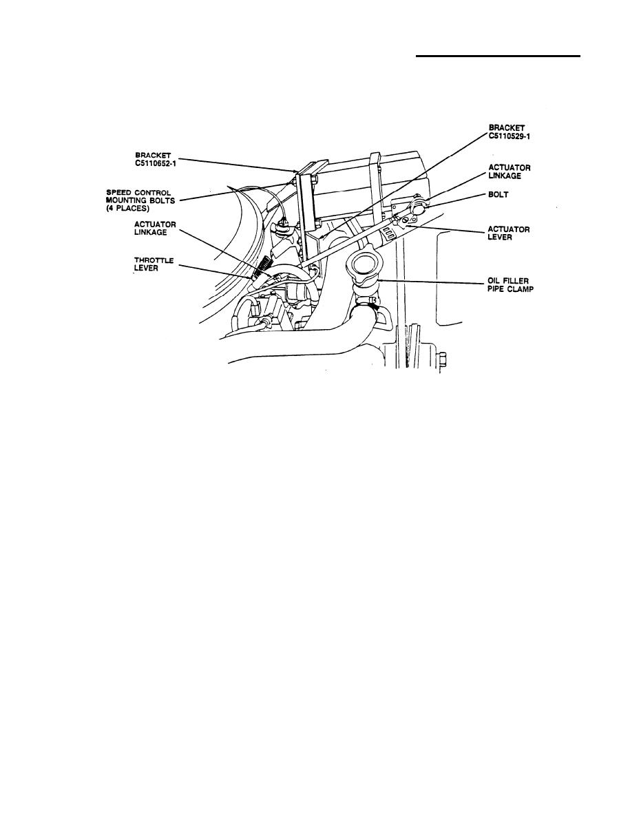
125. Using two 1/2" open end wrenches, remove and retain nut from oil filler
pipe clamp. Attach bracket (item 24, C5110529-1) to oil filler pipe clamp
and tighten nut using 1/2" combination wrench.
126. Using two 1/2" combination wrenches, loosely connect bracket (item 24,
C5110529-1) to bracket (item 27, C5110652-1) with two bolts (item 75,
MS35307-309), nuts (item 43, MS51971-1), flat washers (item 45, AN960C416),
and lock washers (item 47, NAS1640-416). Tighten all hardware loosely
installed in previous steps.
127, Using 1/8" and 5/32" hex key wrenches, attach actuator linkage to vehicle
throttle lever.
128. Install bolt (item 104, MS35309) on actuator lever (item 91, C5131375-1)
and tighten using 3/8" drive ratchet handle, 7/16" socket, and 7/16"
combination wrench.
129. Connect actuator linkage and throttle lever together. Tighten lock nut on
actuator linkage using 3/8" combination wrench. Tighten lock nut on
throttle lever using 7/16" combination wrench.
130. Using 5/32" hex key wrench, attach modified actuator lever to speed control
actuator arm shaft.
39
