SPEED CONTROL GROUP (cont.)
TB 5-2520-551-24
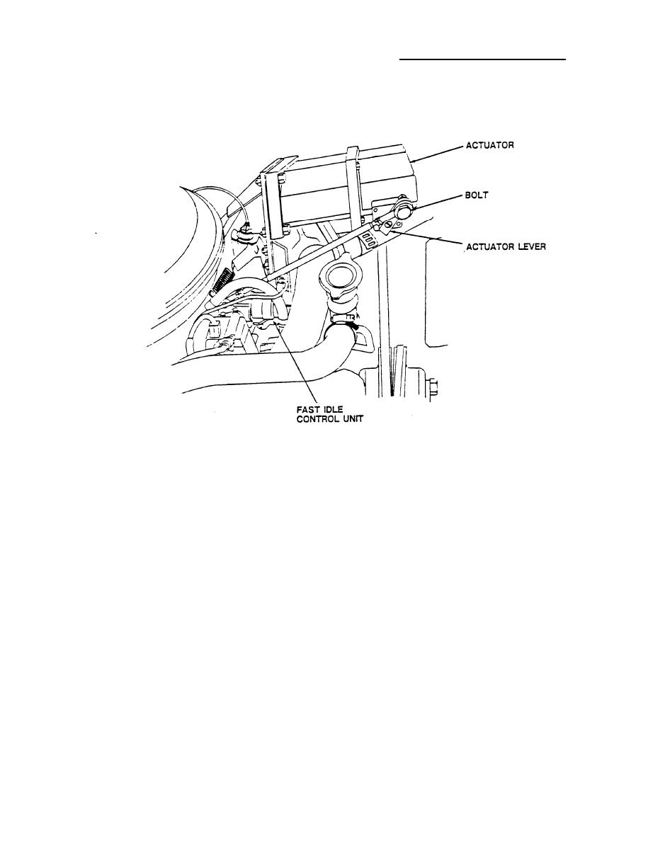
131. Position speed control actuator and controller assembly on (item 27,
C5110652-1) mounting bracket. Mate actuator linkage to linkage on throttle.
Install four nuts (item 36, MS51971-1), bolts (item 74, MS35307-312) flat
washers (item 45, AN960C416) and lock washers (item 47, NAS1640-416)
securing controller assembly to (item 27, C5110652-1) mounting bracket.
Using 3/8" drive ratchet handle, 7/16" socket, and 7/16" combination
wrench, tighten nuts (item 36, MS51971-1).
132. Attach linkage to actuator lever with bolt (item 85, MS35309) lock washer,
(item 47, NAS1640-416) and nut (item 43, MS51971-1). Loosen locking nut,
and thread the large portion of the linkage in or out until the accelerator
Idle is not affected, but the acceler-
is in the fully forward position.
ator moves with the actuator arm. Tighten locking nut.
40


