TB 9-2350-368-25
SECTION V. ELECTRICAL SYSTEM
ELECTRICAL SYSTEM. The electrical system is a 24-volt system using four 6 TL batteries
2-5.
arranged in parallel series. The master switch is installed in the negative return. Four circuit breakers are
used to isolate problems to a particular circuit, reducing troubleshooting time. An electrical transmission
controller selects all of the ranges in the M113A3 transmission. Both 100-amp and 200-amp generator
regulators are provided so that any 6V53 engine may be operated and tested without being damaged. A
connector panel is provided for connecting the 100-amp generator system. An instrument panel is also
provided. See Section VI for instrument panel.
a. 100-Amp Connector Panel
Bill Of Materials
Item
Nomenclature
Part Number
NSN
Qty
1/8" Aluminum Plate
1
9 by 4-1/4 inches (22.86 by 10.795 cm)
1
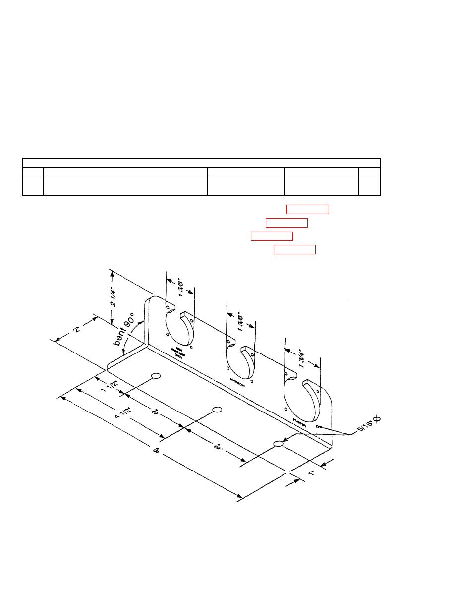
1. Drill two 1-3/8-inch connector holes and eight 5/16-inch screw holes per Figure 2-18.
2. Drill 1-3/4-inch connector hole and four 5/16-inch screw holes per Figure 2-18.
3. Scribe identification information on panel or make labels per Figure 2-18.
4. Drill three 5/16-inch mounting holes spaced three inches apart. See Figure 2-18.
Figure 2-18. 100-Amp Connector Panel


