TM 5-3655-210-12
b. Inspect all hoses, lines, and fittings
(fig. 3-17) for leaks, or damage. See that each
valve bears a numbered identification tag.
for leaks, security of attachment and general
physical condition. Look for spurts of C02
3-27. Fire Extinguisher
snow from compressor packing nut during
operation. Tighten nut if necessary.
Check that the weight of the hand fire
extinguisher (7, fig. 3-18) or (7, fig. 3-19)
c.
Inspect C02 manifolds, piping and
corresponds to the "full weight" stamped on
valves
the body.
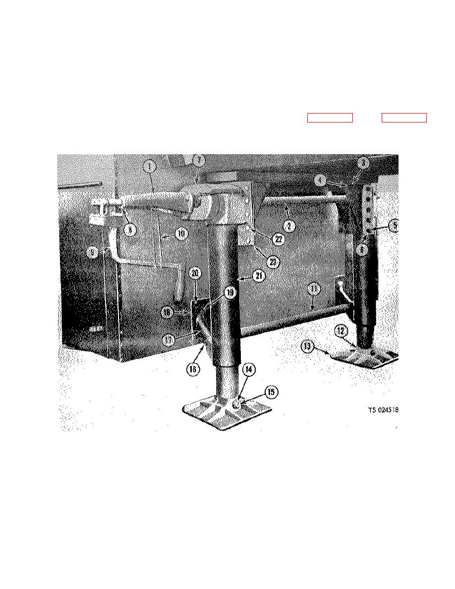
1.
Shaft support
9.
Crank assembly
17.
Diagonal brace
2.
Crankshaft
10.
Crank holder
18.
Plate
3.
Lockwasher
11.
Cross brace
19.
Gasket
4.
Nut
12.
Machine bolt
20.
Screw
5.
Nut
13.
Foot
21.
Landing jack leg
6.
Lockwasher
14.
Nut
22.
Capscrew
7.
Gear box
15.
Washer
23.
Bracket
8.
Fitting
16.
Capscrew
Figure 3-13. Landing gear, installed view.
3-15


