TM 5-3655-210-12
1.
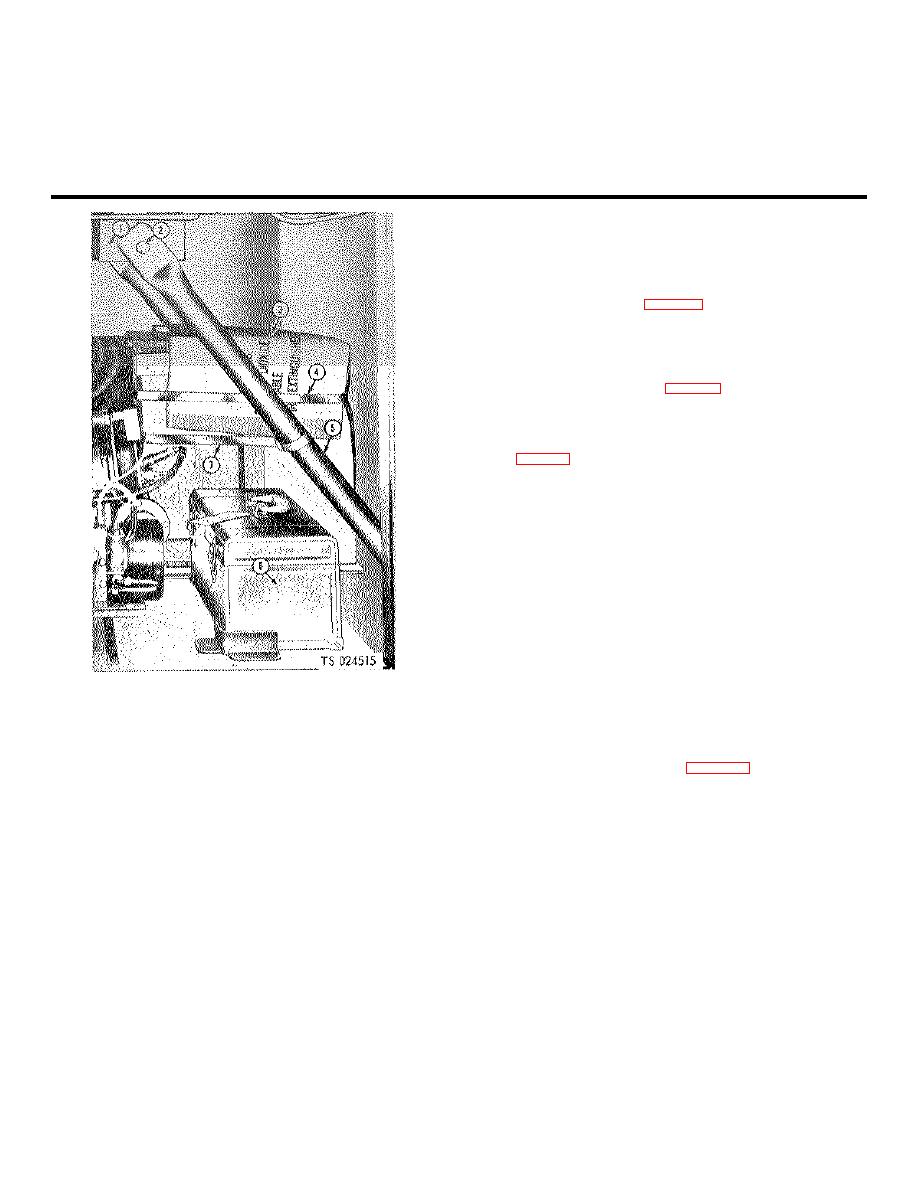
Coolant line
6.
Housing
11.
Coolant line
16.
Pipe union
21.
Wiring harness
26.
Limit switch
2.
Machine screw
7.
Coolant line
12.
Pipe plug
17.
Saddle stand
22.
U-bolt
27.
Limit switch cover
3.
Machine screw
8.
Tube nut
13.
Nipple
18.
Capscrew
23.
Bracket
28.
Lockwasher
4.
Dome light base
9.
Bracket
14.
Tee
19.
Coolant pump
24.
Nut
29.
Coolant line
5.
Dome light lens
10.
Connector
15.
Nipple
20.
Coolant pump lead
25.
Machine screw
Figure 3-9 - Continued.
3-18.
Tires And Tubes
Inspect tires for wear, cuts which damage the cords of the
carcass fabric, and inflation pressure, which should be 75 pounds per
square inch (5.2725 kg per sq cm).
3-19.
Pintle
Check that pintle assembly (7, fig. 3-12) unlatches readily and latches
easily and securely. Clean as necessary to free up sticky mechanism.
3-20.
Landing Gear
W ash or steam clean landing gear for inspection. Check for
loose screws and nuts, damaged threads, corrosion, physical damage,
leaking lubricant from gear box (7, fig. 3-13). Refer maintenance beyond
lubrication to organizational maintenace.
3-21.
Winterization Equipment
Operate conversion and storage gage line heater switches (6
and 7, fig. 3-5). If operating lights (5) do not light, replace bulbs as
follows: To replace a burned out lamp, unscrew the lens from the front of
the light, replace the lamp and screw the lens back in place.
3-22.
Data Plates and Instruction Holders
Inspect data, plates for security of mounting and legibility of
data. Inspect instruction holders for condition and that current copies of
applicable instructions are installed.
3-23.
Motor Starter and Protective Devices
Inspect exterior of starter (fig. 3-14) and reversing switch for general
condition, loose attaching parts and condition of external wiring.
3-24.
Gages, Lines, and Fittings
Inspect instruments and gages for proper indication as
described, security of mounting and freedom from leakage (if applicable).
1. Landing jack brace,
4.
Band
Inspect gages and associated lines for physical damage.
mounting bracket
5.
Landing jack brace
3-25.
Conversion Heater
2. Capscrew
6.
Tool box'
Inspect heater fluid lines (fig. 3-15) and their fittings for leaks.
3. Packing boxes
7.
Band
Check sight glass indications for quantity of heater fluid in tank. Operate
heater and check that exhaust from combustion is free of smoke.
Figure 3-10. Electrolyte and batteries stored for shipment
3-26.
Cylinder Filling Compressor
a.
Service compressor (26, fig. 3-16) according to LO 5-
Electrolyte must cover the plates by at least /4 inch (.635 cm).
3655-210-12.
WARNING
Do not overfill the batteries or splash electrolyte as it is
an acid and can cause personal injury.
(7)
Replace the twelve cell caps and wash off any
acid that may have spilled.
3-17.
Power Transfer Equipment
Check that transfer pump drive belt can be deflected no more
than 1 in. (2.54 cm) at midpoint by thumb pressure; all other belts, no
more than 1/2 in (3.81 cm). Lubricate in accordance with LO 5-3655-
210-12.
3-13


