TM 5-3655-210-12
Section VII. RADIO INTERFERENCE SUPPRESSION
4-18. Definitions
a. Interference. The term "interference" as used
herein applies to electrical disturbances in the radio
frequency range which are generated by the conversion
and storage unit and which may interfere with the proper
operation of radio receivers or other electronic
equipment, or enable the enemy to locate the
equipment.
b. Interference Suppression. The term "interference
suppression" as used herein applies to the methods
used to eliminate or effectively reduce radio interference
generated by the conversion and storage unit.
4-19. General Methods Used To Attain Proper
Suppression.
Essentially, suppression is attained by providing a.
low resistance path to ground for the stray currents. The
methods used to attain suppression include shielding the
ignition and high-frequency wires, grounding the frame
with bonding straps, and using capacitor and resistors
where necessary.
4-20. Interference Suppression Components
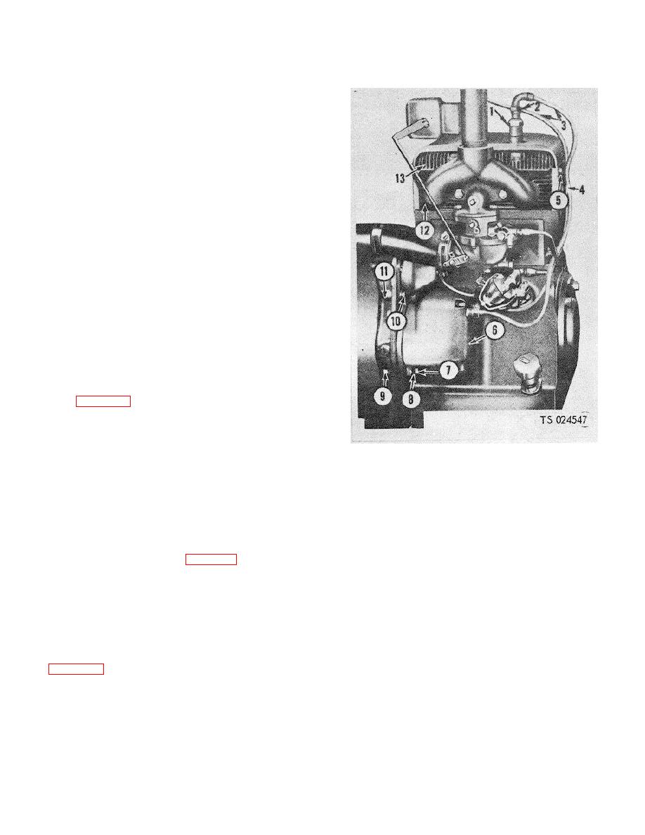
a. Gasoline Engine Spark Plugs and Ignition Cables.
The gasoline engine is equipped with shielded spark
plugs (1, fig. 4-23 1) and shielded ignition cables (3).
Braided metal covering woven around the insulation on
high tension leads are grounded through the magneto to
provide a low resistance path for grounding interference
generated in the circuit.
1.
Shielded spart plug
NOTE
2.
Nut
8. IE toothed lockwasher
3.
Shielded ignition cable
9. Nut
Do not pull on cable or twist braided
4.
Clip
10. Capscrew
shielding. Gently work cable from
5.
Screw
11. Timing gear cover
side to side and free the rubber seal.
6.
Magneto assembly
12. Cylinder block
Do not use sharp tools to install
7.
Capscrew
13. Cylinder head
rubber seals.
Figure 4-28. Ignition suppression components (sheet 1
of 2).
completely inclosed by a metal housing which is
grounded by the mounting. Electrical contact between
the mounting surfaces is accomplished by the use of
(14) on the ignition unit eliminates radio interference by
internal-external tooth lockwashers (8).
Shielded
the ignition unit.
e. Conversion Heater. The conversion heater base
ignition cables (3) carry current from the magneto (6) to
the shielded spark plugs (1).
(8) is grounded by the mounting to the housing.
Electrical contact between mounting surfaces is
conversion heater is equipped with a shielded spark plug
accomplished by the use of internal-external tooth
(6, fig. 4-23 2) and igniter cable (3). Braided metal
lockwashers (12). The pump and blower motor circuit is
around the high tension lead grounds interference from
suppressed by suppressors (14) on the motor.
the circuit.
d. Ignition Unit. The ignition unit (13) is inclosed by
4-21. Replacement Of Suppression Components
a metal housing, grounded to the mounting. Internal-
Refer to figure 4-23 and replace suppression
external tooth lockwashers (9) make electrical contact
components.
between the mounting surfaces. Suppressor
4-27


