TM 5-3655-210-12
Section XIII. 220 VOLT AC ELECTRICAL SYSTEM
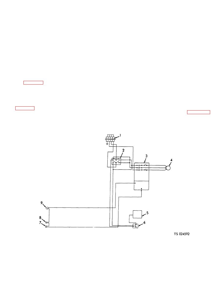
4-56. Description
(high pressure) (1) to open at 240 psi (16.872 kg per sq
cm) to stop the electric motor or gasoline engine. The
The conversion and storage unit is equipped
high pressure switches close to resume operation when
with a 20-volt electrical system, shown schematically in
the pressure drops to 210 psi (14.763 kg per sq cm).
Figure 4-65. This system consists of the electrical
Adjust the switches to the correct settings as indicated
motor, motor starter, reversing switch, high pressure
on the dial by using a screw driver on the adjusting
switch, low pressure switch, refrigeration control
screw.
switches, tank pressure control switch, power
b. Tank Pressure Switch Adjustment. Adjust
receptacle, and electrical motor interlock control.
the tank pressure switches (4) by turning the adjusting
4-57. Pressure Switches
knobs (5 and 6) to the desired setting on the scale. The
correct setting is 305 on the high side (knob 5) and 295
The refrigeration pressure control switches (4
on the low side (knob 6). The pressure switch (8),
and 8, fig. 4-53) and the tank pressure switch are
connected to the conversion heater, is set at 275 on the
identical to the gasoline engine pressure switches and
high side and 260 on the low side.
are adjusted in the same manner, as follows:
a. Regrigeration Compressor Pressure Switch
4-58. Electric Motor Removal
a. Disconnect the 220-volt power cable from
with the adjusting screws on top of the switches (1 and
the power receptacle.
2, fig. 4-53). '.Set the suction pressure switch (2) to
open at zero psi to shut off the engine or electric motor.
securing the correction box cover (27) to the motor (1),
The low pressure suction switches reset to allow
and remove the cover.
operations to resume when the suction pressure rises to
12 psi (.8436 kg per sq cm). Set the discharge switches
1. Power receptacle
4. Electric motor
7. Low pressure switch refrigeration
2. Reversing switch
5. D.C. control panel
8. High pressure switch refrigeration
3. Control box
.6. Gasoline engine-electric motor interlock
9. Tank pressure switch
Figure 4-65. 220-volt wiring schematic.
4-71


