TM 5-3655-210-12
f.
c.
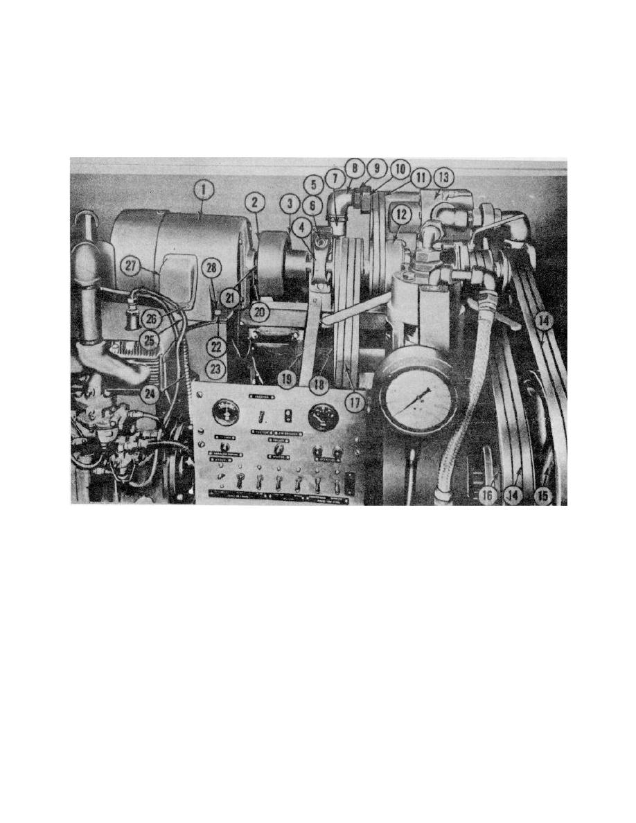
Remove the four nuts (22), lockwashers
Tag the wires and remove the three
(23), and capscrews (28) securing the motor (1) to the
terminal screws which connect the wiring to the motor.
frame (19).
d. Remove the nut (25) securing the cable
g. Slide the motor (1) to the left until the
assembly (24) to the motor.
shaft(21) clears the sleeve (3) and lift the motor from
e. Remove the three screws (2) securing the
the compartment.
clutch cover (20) to the clutch sleeve (3).
1.
Motor, alternating current
11.
Belts, transfer pump
20.
Clutch housing cover
2.
Screw, internal wrenching head
12.
Countershaft assembly
21.
Motor shaft
3.
Clutch sleeve
13.
Transfer pump
22.
Nut, plain
4.
Pillow block bearing
14.
Drive belts
23.
Lockwasher
5.
Plain washer
15.
Flywheel compressor
24.
Cable assembly
6.
Capscrew
16.
Flywheel, cylinder filling unit
25.
Conduit nut
7.
Hose assembly, rubber
17.
Drive belts
26.
Machine screw
8.
Elbow, pipe
18.
Belt, generator drive
27.
Cover
9.
Pipe union
19.
Frame
28.
Capscrew
10.
Nut, pipe union
Figure 4-66. Electric motor, installed view
4-72


