
TM 5-3655-210-12
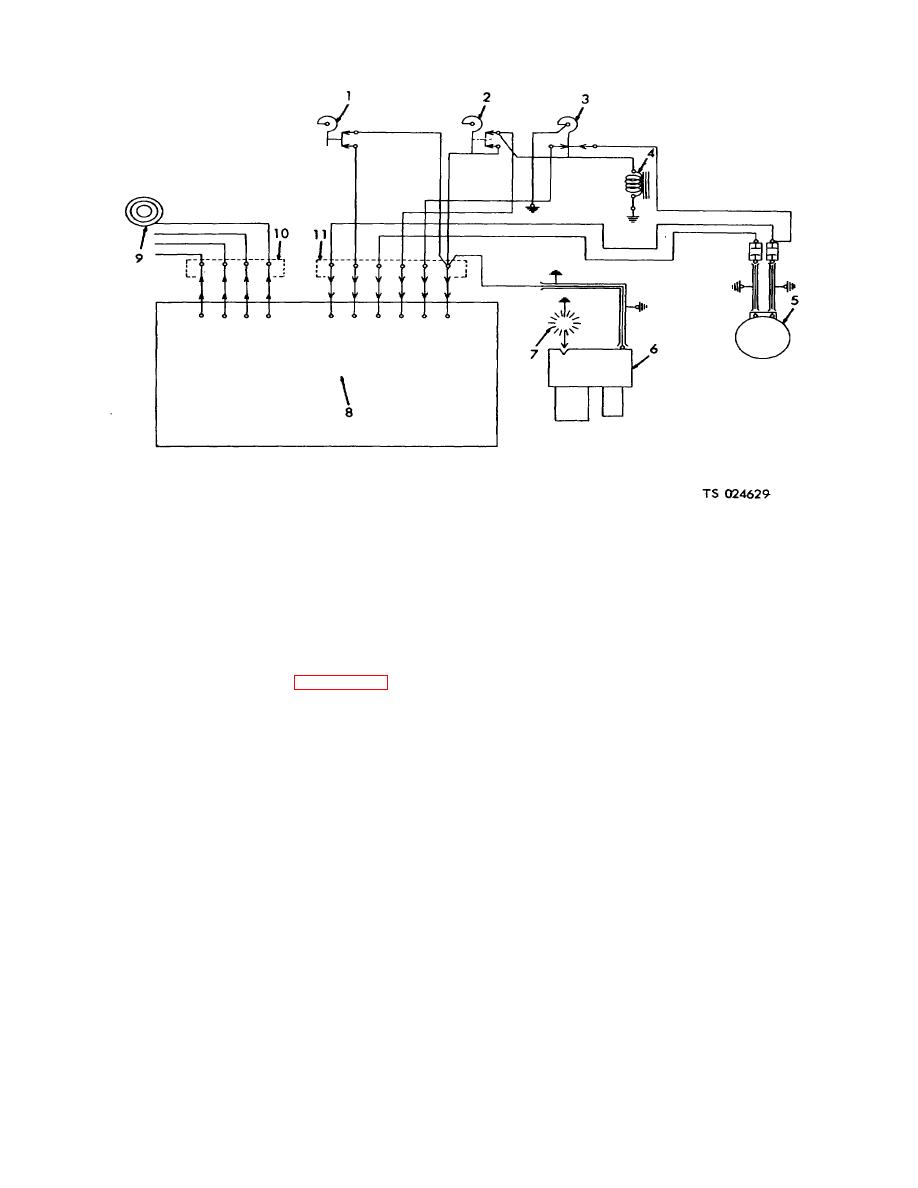
7. Spark plug
1.
Water temperature thermostat
8. Control panel
2.
Water temperature limit switch
9. Water pump
3.
Stack temperature switch
10. Disconnect plug
4.
Solenoid valve
11. Disconnect plug
5.
Pump and blower motor
6.
Ignition unit
Figure 4-102. Heater wiring diagram.
(8) Remove the tee (14, fig. 4-103), and
damaged threads. Replace cracked or badly damaged
nipple (13).
pipes and fittings. Inspect the sight glass for broken
WARNING
glass or any other damage. Replace a damaged sight
Dry cleaning solvent, P-D-680 or P-D-
glass assembly. Test the tank for breaks by filling with
661, used to clean parts is potentially
water. Repair leaks by brazing.
dangerous
to
personnel
and
c. Reassembly.
Reverse the procedure in a.
above.
property. Use in a well-ventilated
4-108. Water Manifold
area as the fumes are dangerous if
a. Removal.
inhaled.
Avoid repeated and
(1) Drain the system.
prolonged skin contact. Do not use
(2) Remove the limit switch cover (27, fig. 4-
near open flame or excessive heat.
103).
Flash point of solvent is 100F.-138F.
(3) Tag and remove the leads.
(38C.-59C.).
(4) Uncouple the lead (20 to the pump motor
b. Cleaning and Inspection. Clean the tank with a
(19).
cloth dampened in a cleaning solvent. Wash all other
(5) Remove the two lines ( and 29).
parts in a cleaning solvent and dry thoroughly. Inspect
the pipes and fittings for cracks, leaks, or
4-115
