
TM 5-3655-210-12
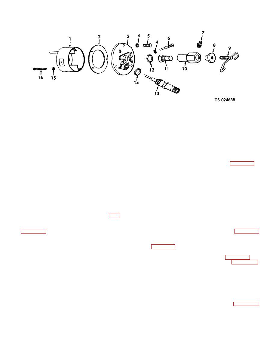
1
Combustion chamber
7
Adapter
12
Packing
2
Gasket
8
Thumbnut
13
Spark plug
3
Combustion head
9
Bail
14
Packing
4
Lock washer
10
Nozzle holder
15
Washer, No
10
6
Cap screw
11
Spray nozzle
16
Machine screw, flat head
6
Electrode, ground
(10) Remove the two cap screws (15) securing
fingers and insert the tissue or cloth between them.
the front end of the manifold to the heater and the two
Permit the points to close and pull the tissue gently from
cap screws (15) securing the rear end and lift out the
between the points. Replace the switch if the points are
manifold and the two gaskets (14). Discard the gaskets.
badly pitted or burnt. Replace the switch if any other
(11) Pull the disconnect plug (31, fig. 4-106).
damage is noticed.
(12) Remove the four cap screws (11) that
NOTE
secure the plate (13) to the combustion head.
(13) Remove the four machine screws and
Do not use point file or emery cloth in
washers securing the blower (15) to the pump (10) and
cleaning points.
slide the blower (15), plate (13), and gasket (14) out and
c. Reassembly and Installation.
Reverse the
away from the heater.
removal and disassembly given in a. above.
(14) Remove the two fuel tubes (6 and 7).
4-114. Wiring And Ignition Unit
(15) Disconnect and tag the taped leads (19).
(16) Remove the four cap screws (24) securing
a. Removal
the pump (10). Remove the fuel pump from the heater.
(1) Remove the disconnect plug (31, fig.
(17) Remove the wire to the solenoid valve
4-106).
(23).
(2) Tag the leads and remove the two screws
(18) Loosen the two tube nuts (18, fig. 4-100)
(4, fig. 4-108) securing the leads to the switch to be
and remove the tubes.
removed.
(19) Remove the three fuel tubes (6, 7, and
(3) Unscrew the switch (1) from the heater
22, fig. 4-106) by unscrewing the six tube nuts (9) and
using two wrenches, with one on the hex part of the
lifting out.
switch and the other on the hex part of the heater pipe.
(20) Remove the fuel tube (17, fig. 4-108).
(4) Remove six screws (5) securing the cover
(21) Remove the two screws (8, fig. 4-106),
to the switch and lift off the cover.
nuts, and washers securing the fuel filter bracket.
(5) Remove the limit switch cover (27, fig.4-
(22) Remove the four nuts, washers, and cap
112).
screws (24) securing the manifold to the pump assembly
(6) Tag and remove the leads.
(10).
(7) Uncouple the lead (20) to the pump motor
(23) Remove the two cap screws and lock
(19).
washers securing the manifold to the base. Remove the
(8) Remove the two lines (7 and 29).
manifold.
(9) Unscrew the two tube nuts (10, fig. 4-
(24) Remove the two screws (10, fig. 4-108)
100) ;securing the line (21) and remove the line.
securing the stack switch cover (11) to the stack and
remove the cover.
4-125
