
TM 5-6640-212-14
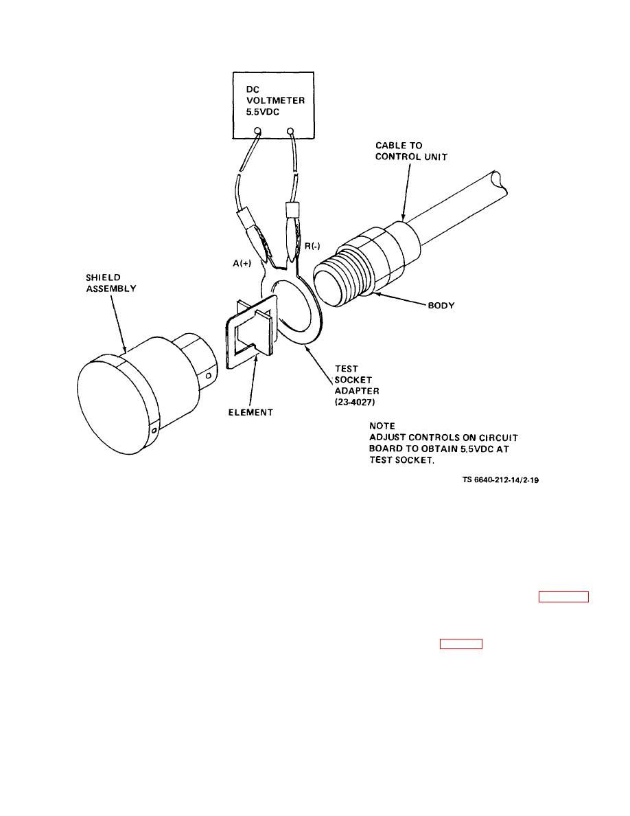
Figure 2-19. Test Setup, Element 5.5 VDC Check
(2) Detector voltage being set abnormally low.(3)
(4) If voltage is still incorrect after element
replacement, replace the printed circuit board (B, fig. 2-
(3) Excessive negative meter drift.
18).
g. Power Supply. The power supply is designed to
b. Troubleshooting Refer to table 2-2 for
maintain a constant voltage to the detector circuits
troubleshooting procedures.
despite variations in the input voltage. If the voltage at
2-23. Analytical Balance.
test points B on the printed circuit board is incorrect and
a. Description. The analytical balance (fig. 2-20),
cannot be brought to the correct value by adjusting the
voltage adjuster, proceed as follows:
designed to meet the requirements specified in ASTM
(1) Make sure that the module is fully inserted into
Method D2276 (TM 10-1166), is located on the right-
its socket.
hand counter adjacent to the entrance door, above
drawers K1 and K2 (fig. 1-2). It has an automatic
(2) Check fuse (or circuit breaker). Light will be off
preweighing and single-knob taring system.
It
on all modules if fuse is burned out (or circuit breaker
incorporates full 1000-milligram optical range with digital
has tripped).
readout. The numbers to be read on the optical scale
(3) Check
the
detector,
and
replace
if
appear in a clear window while all neighboring values are
necessary.
visible, but subdued, through a green filter.
2-36
