TM 9--2520--215--34
0029 00--12
MAIN CONTROL VALVE ASSEMBLY REPAIR – CONTINUED
0029 00
ASSEMBLY – Continued
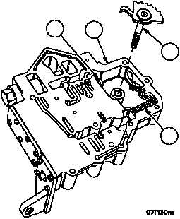
14. Insert range selector lever (9) into control valve body assembly (4). Compress the detent spring (11) with a
screwdriver when aligning lever with range selector valve assembly (16).
4
16
9
11
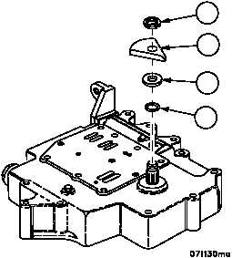
15. Install seal ring (8), thrust washer (7), shift position indicator (6) and new snap ring (5).
6
7
8
5