TM 9-4910-663-34
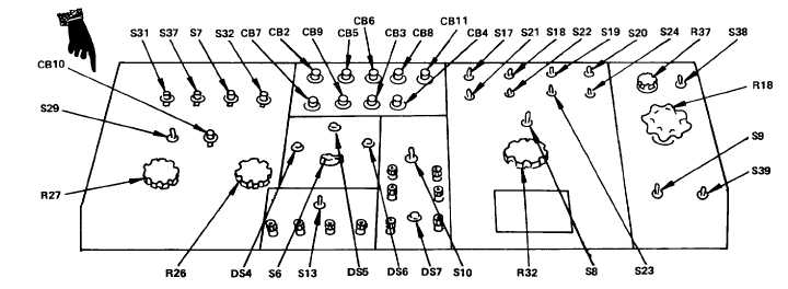
Legend for fig 2-5:
CB2
Circuit Breaker
CB3
Circuit Breaker
CB4
Circuit Breaker
CB5
Circuit Breaker
CB6
Circuit Breaker
CB7
Circuit Breaker
CB8
Circuit Breaker
CB9
Circuit Breaker
CB10
Circuit Breaker
CB11
Circuit Breaker
DS4
6 Volt Indicator Light
DS5
12 Volt Indicator Light
DS6
24 Volt Indicator Light
DS7
Contact Closure Indicator Light
R18
Starter Rheostat Control
R26
Field Current 0-30 Amps (Max) Control
R27
Field Current 0-5 Amps (Max) Control
R32
Variable Load Control
R37
Voltage ADJ Control
S6
Battery Circuit Selector Switch
S7
Polarity Reversing Switch
S8
Master Load Disconnect Switch
S9
Starter Test Switch
S10
DC Variable Volts Switch
S13
Regulator Check Fixed Resistance Method Switch
S17
Load Selection Switch
S18
Load Selection Switch
S19
Load Selection Switch
S20
Load Selection Switch
S21
Load Selection Switch
S22
Load Selection Switch
S23
Load Selection Switch
S24
Load Selection Switch
S29
Fine Control 0-5 Amps (Max) Switch
S31
External Field Exciter AC System Switch
S32
Field Current Switch
S37
Generator Field Switch
S38
Field Shorting Switch
S39
AUX Start Switch
Figure 2-5. Control and rheostat panels, controls and indicators.
Change 1 2-63