
TM 5-3655-210-12
(4) Observe the pressure reading on the gage. The
(8) Position the fuel tube (9) on the carburetor and
proper reading is between 3 and 4 lbs. (1.35 and 1.8
fuel pump and secure with the two tube nuts (8).
kg).
(9) Screw the thumb nut (17) into position on the
(5) If this reading is not obtained, check the fuel
bail (16).
tubes and fitting between the fuel pump and the fuel
(10) Position the bail in the cover (3).
tank for leaks.
(11) Swing the bail to one side and place the
(6) Remove the pressure tester and adapter.
screen (20), gasket (19) and the sediment bowl (18) into
(7) Position the fuel tube (9, fig. 4-31) on the
position. Swing the bail (16) back into position under
carburetor and fuel pump and secure with the two tube
the sediment bowl and secure with the thumb nut (17).
nuts (8).
(12) Position the main fuel tube on the fuel filter
and secure with the tube nut (8, fig. 4-31).
4-29. Fuel Pump And Fuel Strainer (Serial Nos. L-
d. Test.
1666-T through L-1668-T).
(1) Remove the fuel tube (11, fig. 4-24) from the
a. Removal and Disassembly.
carburetor (16) and fuel pump (6, fig. 4-31).
(2) Install the pressure tester between the fuel
(1) Loosen the two tube nuts (10, fig. 4-32)
pump and the carburetor.
securing the fuel tube (11) to the carburetor (16) and the
(3) Start the engine and run at idle speed.
fuel
pump,
and
remove
the
tube.
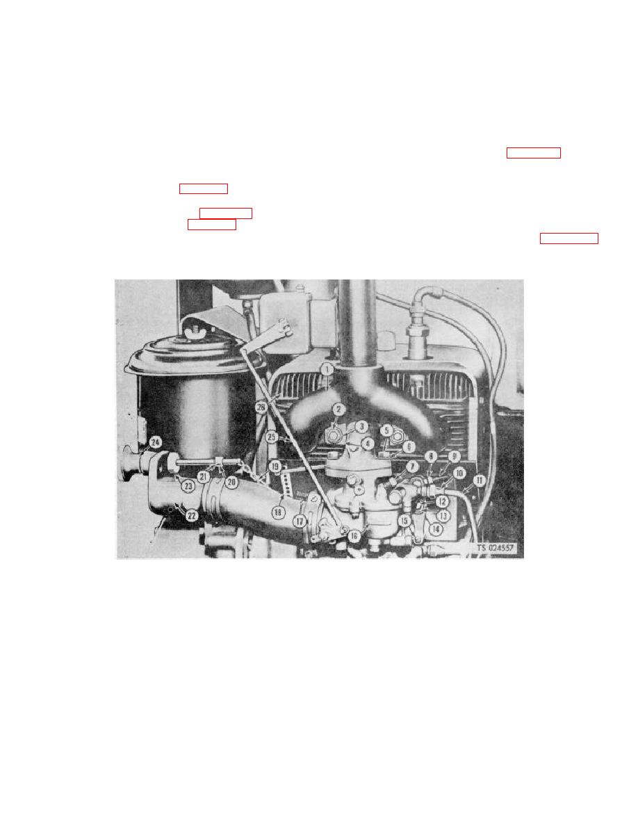
1.
Exhaust manifold
10.
Tube nut
19.
Chain
2.
Nut
11.
Fuel tube
20.
Setscrew
3.
Lockwasher
12.
Support pin
21.
Stop collar
4.
Saddle washer
13.
Cotter pin
22.
Air cleaner mounting bracket
5.
Capscrew
14.
Governor control lever
23.
Locknut
6.
Lockwasher
15.
Screw
24.
Governor control
7.
Adjusting needle screw
16.
Carburetor
25.
Throttle rod
8.
Adjusting nut
17.
Spring
26.
Cylinder block
9.
Governor control rod
18.
Cross shaft lever
Figure 4-32. Governor controls, installed view.
4-38
