
TM 5-3655-210-12
(2) Remove the four nuts (7) and lock
washers (6) securing the hold-down bars (5) and remove
the bars.
(3) Lift the batteries from the battery retainer
(13)
b. Installation. Reverse procedure in a. above.
c. Testing. Refer to TM 96140-200-15.
4-43. Starter and Solenoid
a. Removal.
(1) Remove the battery ground lead (2, fig. 4-
49) from the battery.
(2) Remove the nut (17, fig. 4-39) from the
solenoid (26) releasing the battery lead (10). Remove
the regulator lead (20) wire.
(3) Remove the nut (21), releasing the switch
lead (20) and the automatic choke lead (22).
(4) Remove the nut (10, fig. 4-50) and lock
washer securing the starter lead (16) to the solenoid (11)
and remove the lead.
(5) Remove the nut (18) and lock washer
securing the lead (16) to the starter (17).
(6) Remove the two machine screws (12) and
lock washers securing the solenoid (11) to the shroud
(9). Lift off the solenoid.
(7) Remove the two caps crews (20) and lock
washers (21) securing the starter bracket(19)to the
crankcase (22). Remove the bracket from the starter.
(8) Remove the three cap screws (15) and
TS 024572
lock washers (14) securing the starter (17) to the timing
gear plate (13). Remove the starter from the plate.
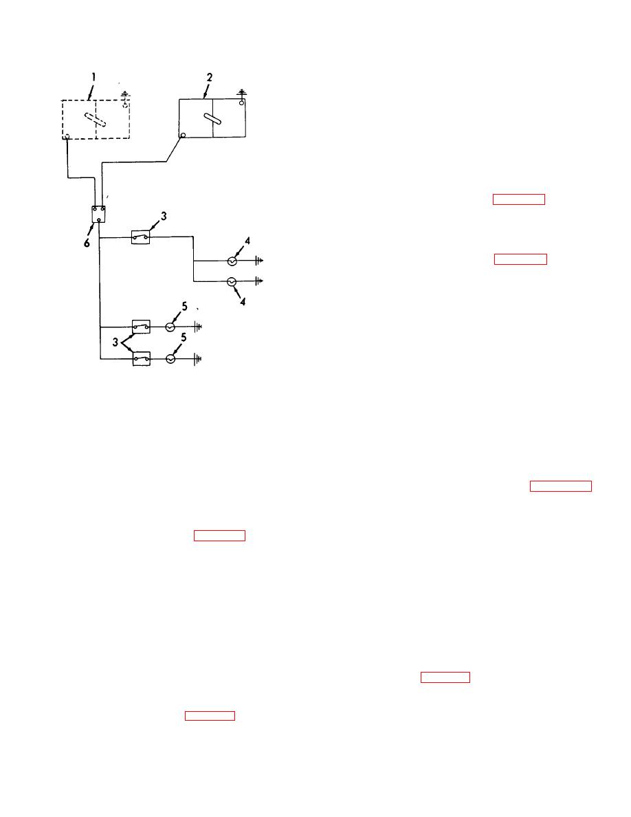
1. Tractor batteries
4. Power compartment dome
b. Installation. Reverse the procedure in a above.
lights
2. Trailer batteries
5. Storage compartment dome
4-44. Generator Regulator
lights
a. Removal.
3. Dome light switches 6. "Tractor-trailer" control
(1) Remove the screw (25, fig. 4-51)
switch
releasing the lead (24) from the regulator (20).
Figure 4-46. Dome light schematic.
(2) Remove the two wiring harnesses (15 and
19) from the regulator.
(3) Remove the four cap screws (21) nut, and
lock washers securing the regulator (20) to the mounting
cut-out to prevent reverse current flow from the battery
plate (22). Remove the regulator.
to the generator when the generator is not operating. It
(4) Remove the two cap screws (23), nuts,
also contains a voltage limiter set at 28 1 volt. A
and lock washers (26) securing the mounting plate (22)
current limiter, incorporated as protection for the
to the frame (27). Remove the plate.
generator, is set for maximum output of 18 amperes.
b. Installation. Reverse the removal procedure in a
above.
required by the equipment and maintains the batteries
(21) in a fully charged condition for cranking the
4-45. Generator
gasoline engine.
a. Generator Removal.
h. Two 12-volt batteries connected in series supply
(1) Loosen the coupling nut securing the
power to the 24-volt DC system. The negative terminal
wiring harness (15, fig. 4-51) to the generator (31) and
of the battery is the ground.
disconnect the harness.
4-42. Batteries
(2) Remove the cap screw (13) securing the
a. Removal.
generator (31) to the adjusting bracket (14).
(1) Loosen the nuts (4, fig. 4-49) securing the
leads (2, 8 and 9) to the batteries (12) and lift the lead
free of the battery.
4-53
