
TM 5-3655-210-12
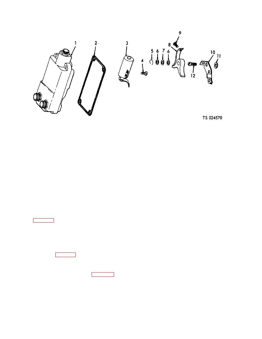
1.
Magneto cover
5.
Lock
9.
Screw
2.
Gasket
6.
Washer
10.
Fixed contact
3.
7.
Washer
11.
Aliening washer
4.
Screw
8.
Breaker arm
12.
Screw
Figure 4-44. Condenser and breaker points, exploded view.
Section XII. 24 VOLT ELECTRICAL SYS. TEMS ENGINE AND VEHICULAR
4-41. Description
suction pressure. The high pressure switch opens to
a. The 24 volt electrical system is comprised of
stop the engine when the discharge pressure reaches
240 psi (16. 872 kg per sq. cm). The low pressure
three circuits. (fig. 4-45).
b. The running light circuit is operated from the
switch will close again when the suction pressure rises
to 12 psi (. 8436 kg per sq. cm), and the high pressure
towing vehicle batteries and comprises the front trailer
switch will close when the pressure drops to 240 psi (16.
receptacle, the rear receptacle, the trailer tail lights, the
872 kg per sq. cm). The tank pressure control switch
service clearance lights, and the blackout service lights.
c. The dome light circuit is powered by either the
(10) closes the circuit to the gasoline engine at 305 psi
(21. 4415 kg per sq. cm) and opens the circuit when the
tractor (1, fig. 4-46) or trailer (2) batteries through the
pressure drops to 295 psi (20. 7385 kg per sq. cm). An
TRACTOR-TRAILER control switch (6). The other
alarm pressure switch (14) is provided for each pressure
components are the three dome light switches (3), the
vessel, which closes the circuit to the alarm bell (15)
storage compartment dome lights (5) and power
when tank pressures exceed 325 psi (22. 8475 kg per
compartment dome lights (4).
d. The DC control circuit is controlled through the
sq. cm) or are below 250 psi (17. 575 kg per sq. cm).
e. When the unit is set for automatic operation,
trailer batteries and consists of the toggle switches (13,
using the gasoline engine for power, the automatic
9, 8, 7, 6, 11, and 12, fig. 4-47) heater failure lights (10,
engine control (17) will crank the engine for a
14), the gage line heater lights (5), ammeter (1) circuit
predetermined time interval. If the engine fails to start
breaker (3), and the fuel gage (4), all mounted on the
after the cranking cycle, the control will cease to
DC control panel (fig. 4-47).
Two refrigeration
function and a failure, light will light on the control panel.
compressor pressure switches (22, 23, fig. 4-48) are
Power is supplied to the control when the tank pressure
connected to the ignition system of the engine. The low
control switches close.
pressure switch (22) opens to ground out the magneto
to stop the engine at zero pounds per square inch
4-51
