
TM 5-3655-210-12
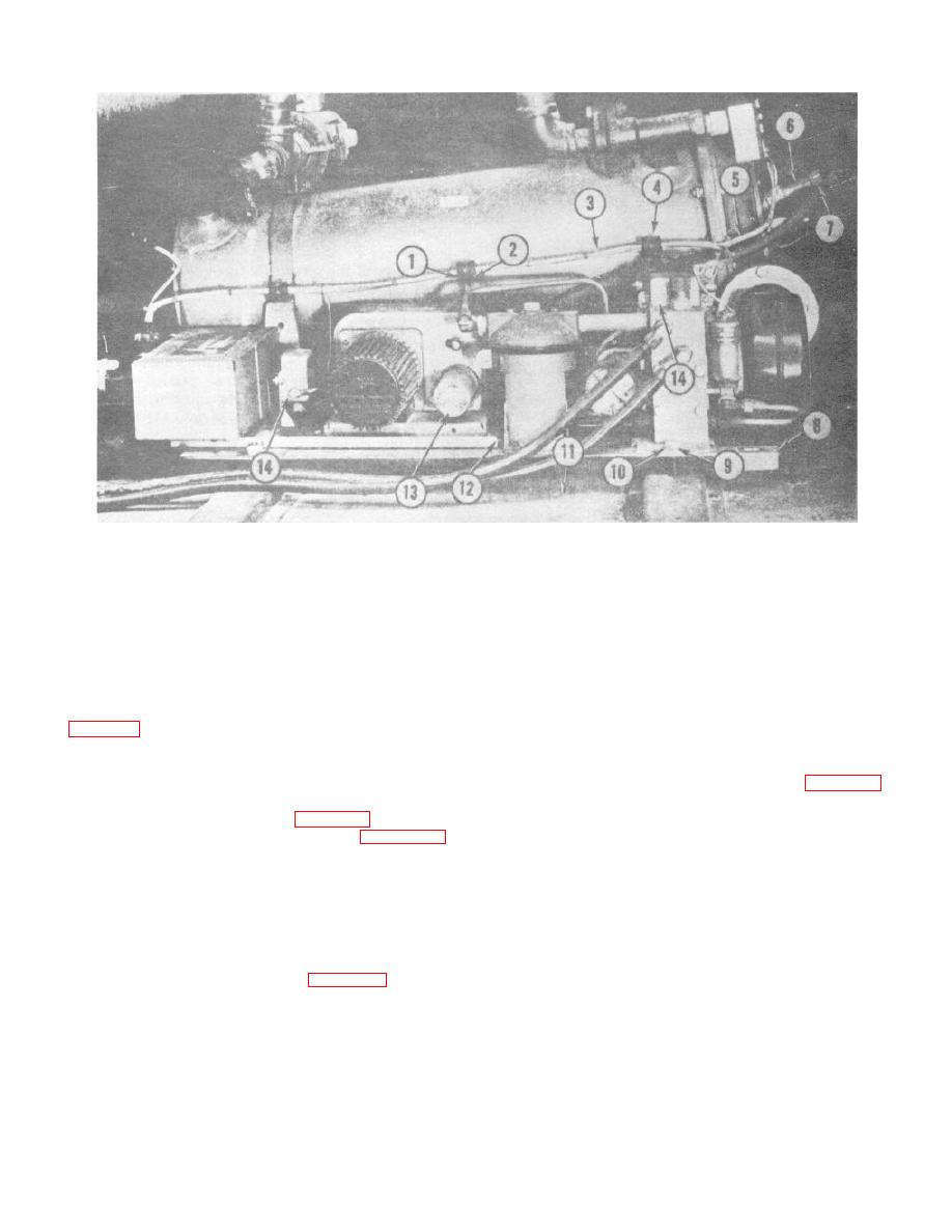
1.
Nut
6.
Shielded spark plug
11.
Housing
2.
Machine screw
7.
Nut
12.
IE toothed lock washer
3.
Shielded ignition cable
8.
Heater base
13.
Ignition unit
4.
Clip
9.
IE toothed lock washer
14.
Radio interference suppression
5.
Combustion head
10.
Cap screw
Figure 4-40. Ignition suppression components (Sheet 2 of 2)
(3) Continue to turn the engine until the edge
(1) Remove the ground and spark plug
(6, fig. 4-41) of the vane (4) marked X is in line with the
cables.
vertical center line mark (5) on the shroud (1). Leave
(2) Remove the magneto cover and gasket
the' flywheel in this position as the number one piston is
from the magneto.
now on top dead center. Note the flywheel (2) is marked
(3) Remove the terminal screw (3, fig. 4-43).
with "DC" (7) near the marked vane.
(4) Remove the breaker arm lock (7) and
(4) Remove the plug (20, fig. 4-34).
washers (5), and take the breaker arm (8) off the pin (6).
(5) Turn the magneto gear (3, fig. 4-42)
(5) Remove the aligning washer (11, fig. 4-
clockwise until the impulse coupling snaps.
44) from the pin.
(6) Hold the gear in this position and mount
WARNING
the gasket and magneto to the engine meshing the
Dry cleaning solvent, P-D-680 or P-
gears so that the "X" marked tooth (4) is centrally
S661, used to clean parts is
located in the inspection hole.
potentially dangerous to personnel
(7) Replace the attaching hardware, and the
wiring.
and property.
Use in a well-
(8) Whiten tip of vane (4, fig. 4-41) next to
ventilated area as the fumes are
timing mark (7) on the engine flywheel with chalk or
dangerous if inhaled.
Avoid
paint. Connect a timing light to the engine. With engine
repeated and prolonged skin contact.
operating at governed speed, timing light should cause
Do not use near open flame or
vane (4) to appear stationary in alignment with mark (3)
excessive heat.
Flash point of
in shroud.
solvent is 100F. -138F. (38C. -59C.
(9) Install the inspection hole plug (20, fig. 4-
).
34) in the timing gear cover and replace-the screen.
d. Breaker Point and Condenser Removal.
4-49
