TM 5-3655-210-12
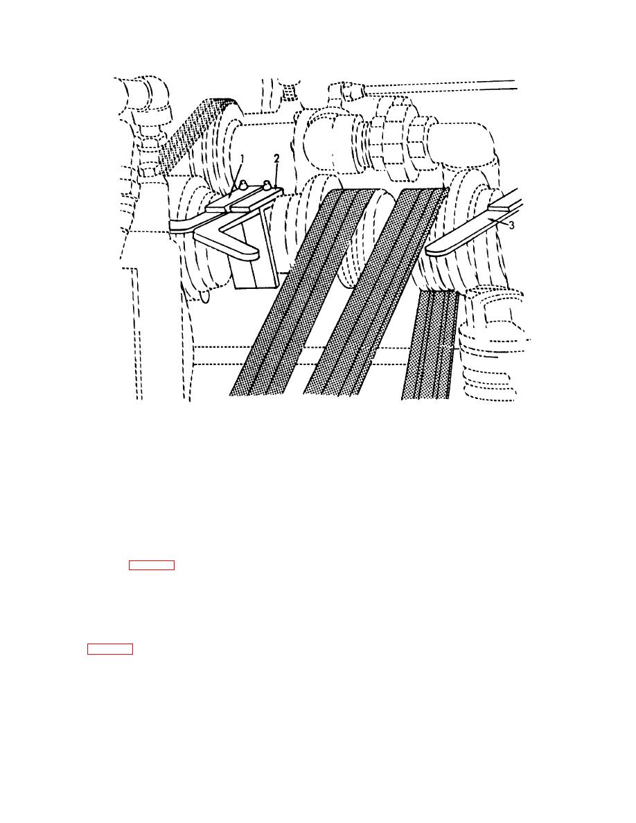
1. Transfer pump clutch shifter
3. Refrigeration compressor clutch shifter
2. Cylinder filling compressor clutch shifter
Figure 2-3. Clutch controls, installed views
z. Clutch Shifters. The three clutch shifters are
side of the power compartment. It is a three-
pole, double-throw switch controlling the rotation of the
mounted on the countershaft in the power compartment.
electric motor.
They are manual controls to engage the three clutches
x. Conversion Heater Vibrator Switch.
The
which operate the transfer pump (1, fig.2-3),
vibrator switch (20, fig. 2-5) is located on the ignition
refrigeration compressor (3) and the cylinder filling
unit of the conversion heater. This switch is safety wired
compressor (2).
aa. Governor Controls. The governor control (24,
at the factory. The vibrator is wired with two sets of
contacts. When the normal set of contacts have failed
fig. 2-10) is located on the left side of the gasoline
the wire must be cut to pull the switch out. The vibrator
engine. It controls the speed of the gasoline engine.
is then operating on the reserve contacts.
y. Battery Circuit Breaker. The battery circuit
2-3.
Operation Under Usual Conditions
breaker (3, fig. 2-2) is mounted on the engine control
a. General.
panel and provides overload protection for voltage
Instructions in this section are
sensitive components.
published for the use of the personnel responsible for
the operation of the conversion and storage unit.
2-4


