
TM 5-3655-210-12
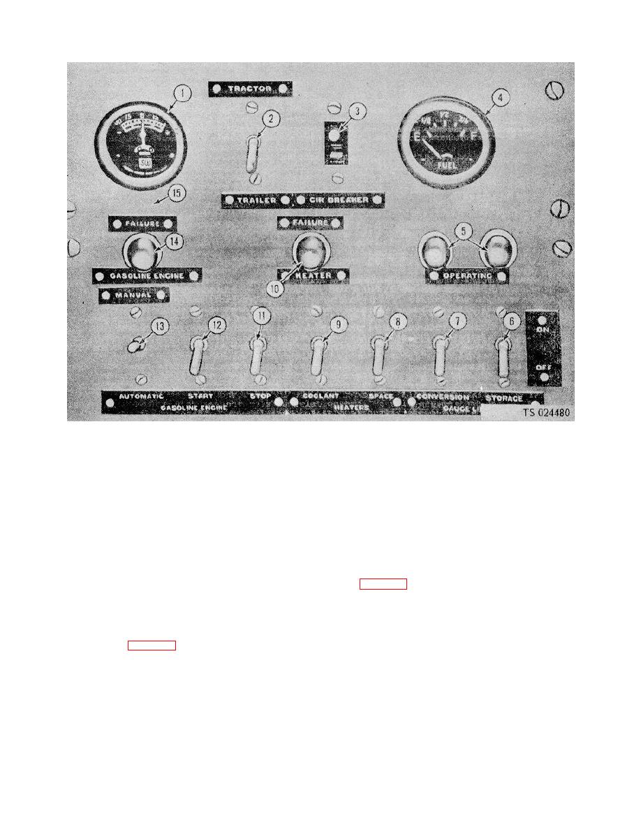
1.
9
Conversion heater control switch
2.
Electrical control switch (tractor or trailer)
10
Conversion heater failure light
3.
Circuit breaker
]1
Gasoline engine manual stop switch
4.
Fuel indicator
12
Gasoline engine manual starter switch
5.
Gage lines operating lights
13
Gasoline engine control switch for automatic or
manual
6. Storage vessel gage line switch
control
7. Conversion vessel gage line switch
14
Gasoline engine failure light
8. Compartment heater control switch
15
Engine control panel
Figure 2-2. Engine control panel
s. Battery Selector Switch. This switch (2, fig. 2-
(27, fig. 2-8) is located in the crankcase of gasoline
engine, on the right side at the governor mounting. It
2) is mounted on the engine control panel. It is a single-
primes the carburetor when starting the engine.
pole, double-throw switch to supply power to the unit,
v. Electric Motor Starting Switch. The electric
from either the tractor or the trailer batteries.
t. Gasoline Engine Control Switch. The engine
motor starting switch (fig. 2-9) is located on the left wall
of the power compartment. This switch is used for
control switch (13, fig. 2-2) is located on the engine
either manual or automatic starting of the electric motor.
control panel. It is a double-pole, double-throw switch to
A reset button is located below the operating switch, to
set the engine for either "manual" or "automatic"
manually reset the switch should an overload occur.
starting.
w. Electric Motor Reversing Switch. The electric
u. Carburetor Priming Lever (Serial Nos. L-14
75Tthrough L-1478-T). The carburetor priming lever
motor reversing switch (fig. 2-9) is located on the
2-3
