TM 5-3655-210-12
3-12.
Muffler And Exhaust Pipe Inspection
Refer to Figure 3-4 and inspect the muffler (1) for leaks or
signs of rusting through the metal.
NOTE
Surface rusting, if it doesn't weaken the muffler to the point of
causing structural failure, is not enough to justify replacement
of the muffler.
Inspect muffler, elbows (2), pipes (3, 4, and 14) for security of mounting,
tight joints, and freedom from corrosion.
3-13.
Cooling System Inspection
Refer to Figure 3-4 and inspect the cooling air shroud (5) and
related sheet metal ducting for security of attachment and freedom from
damage. Check flywheel cover (6) for any obstruction to air flow, such as
dust accumulation.
3-14.
Engine Control Panel Inspection
Refer to figure 3-5 and check that fuel gage (4) indicates
quantity of fuel in tank (should be full before operation), and ammeter (1)
indicates zero. Check for loose or damaged panel components.
3-15.
Lights
a.
Stop and Taillights.
(1)
To remove either blackout or service stop and
taillights (11 and 15, fig. 3-6) uncouple wire connectors (14) and tag
leads for identification, then remove capscrews (12) and lockwashers (13)
to free blackout units, or screws and nuts attaching service units.
Reverse this procedure to install.
(2)
To replace lamps, loosen screws, remove door (1,
fig. 3-7) and remove defective lamp by pressing in while turning lamp to
left, to disengage lamp base from socket, then remove lamp. Install new
lamp by reversing removal procedure above.
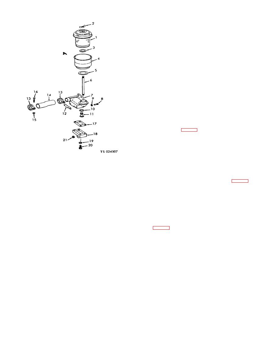
1.
Cap and filter assembly
12.
Gasket
NOTE
2.
Wingnut
13.
Hose clamp
Procedure above is typical for both service and blackout
3.
Gasket
14.
Hose
taillights.
4.
Oil cup assembly
15.
Nut
5.
Gasket
16.
Screw
b.
6.
Stud
17.
Gasket
screws (11), door (1), lens (2) and press and turn lamp left to release.
7.
Air cleaner bracket
18.
Breather
Reverse these steps to complete operation. To replace entire light
8.
Machine bolt
19.
W asher
assembly proceed as follows:
9.
Lockwasher
20.
Screw
(1)
Remove door and lens as given above. Inside
10.
Gasket
21.
Preformed packing
trailer body, at light to be replaced, disconnect electrical connector by
11.
Breather
pressing two halves together while twisting them.
(2)
Remove screws (7) and take off clearance light
Figure 3-2. Air cleaner, exploded view.
and gasket (9). Reverse this procedure to install light.
c.
Dome Lights.
swing bail (16) aside. Remove bowl, gasket (19) and screen (20).
(1)
To remove dome lights, disconnect wire connector
c.
Clean screen of accumulated dirt, and reassemble,
(10, fig. 3-9), remove three screws (2) holding base (4) to roof of
using a new gasket (19).
compartment. Reverse procedure to install.
d.
Open shut-off valve and check for leaks at gasket.
Tighten thumbnut until any leak stops.
3-6


