
TM 5-3655-210-12
(3) Replace the oil tube.
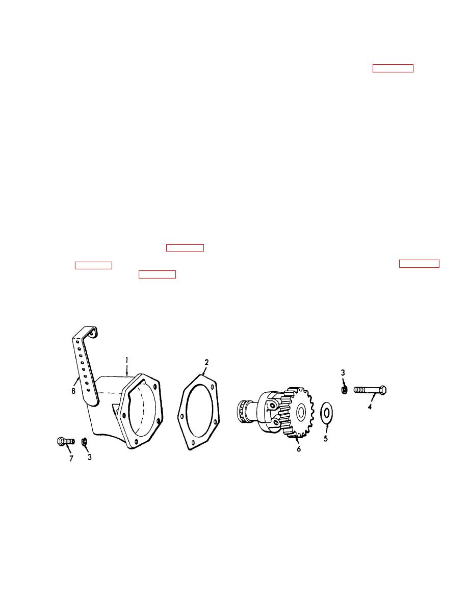
the shaft that is pressed into the timing gear cover (21,
(4) Replace the spring (17, fig. 4-24) in the
fig. 4-27).
WARNING
proper hole in the lever (18).
Dry cleaning solvent, P-D-680 or P-S-661, used to
(5) Slide the governor control rod into the lever
clean parts is potentially dangerous to personnel
(18) and secure with the cotter pin.
d. Adjustment. The rod from the governor to the
and property. Use in a well-ventilated area as the
fumes are dangerous if inhaled. Avoid repeated and
carburetor must be adjusted to the proper length. With
the engine stopped, the governor spring (17) will hold
prolonged skin contact. Do not use near open
the flyweights "IN" and the rod must be of such length as
flame or excessive heat. Flash point of solvent is
to hold the carburetor throttle wide open at that point.
100F.-138F. (38C.-59C.)
To check the accuracy of this adjustment, remove the
b. Cleaning, Inspection and Repair. Wash all parts
cotter pin securing the rod to the lever (18) and slide the
thoroughly in a cleaning solvent. Inspect the capscrews
rod from the lever. Push the rod toward the carburetor
for damaged threads. Clean the gasket mating surfaces
as far as possible. This will fully open the throttle. The
on the governor housing and the gear cover spacer.
bent end of the throttle rod should now line up exactly
Inspect the housing for cracks and leaks. Inspect the
with the hole in the lever (18). If it does not, screw the
shim washer for excessive wear. Inspect the flyweight
rod in or out of the swivel block on the carburetor lever
and thrust sleeve assembly for bearing, gear, and
until it is lined up properly. Position the rod in the
bushing wear. Replace all damaged parts. Replace the
governor lever and secure with the cotter pin.
gasket.
4-28. Fuel Pump And Fuel Strainer (Serial Nos.L-
c. Installation.
1475-T through L-1478-T.
(1) Position the shim washer (5, fig. 4-29) and
a. Removal and Disassembly.
the flyweight assembly (6) on the shaft in the timing
(1) Loosen the two tube nuts (10, fig. 4-24)
gear cover (21, fig. 4-27).
securing the fuel tube (11) to the carburetor (16) and the
(2) Position the gasket(2, fig. 4-29) and housing
fuel pump and remove the tube.
(1) and secure, with the four lockwashers (3), the two
(2) Unscrew the tube nut securing the main fuel
machine bolts (4) through the timing gear cover and the
tube to the fuel strainer and push the fuel tube out of
two capscrews (7) through the governor housing.
the way.
TS 024554
1.
Housing
5.
Shim washer
2.
Gasket
6.
Flyweight and thrust sleeve assembly
3.
Lockwasher
7.
Capscrew
4.
Machine bolt
8.
Control arm
Figure 4-29. Governor, partially exploded view.
4-35
