
TM 5-3655-210-12
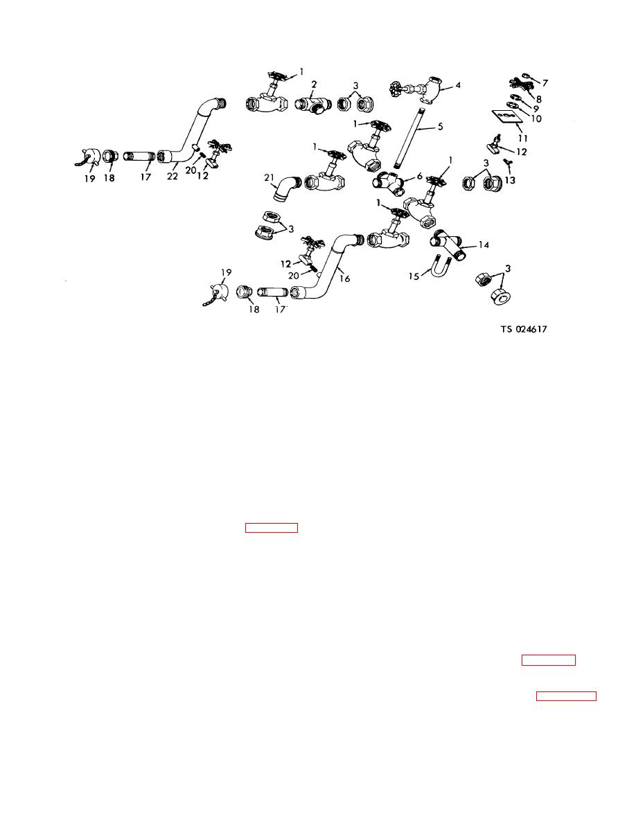
1.
Valve
2.
Tee assembly
9. Lockwasher
16. Elbow assembly adapter
3.
2/3 union
10. Flatwasher
17. Nipple
4.
Valve
11. Bracket
18: 1/3 union
5.
Nipple
12. Valve (3) (includes items (7) and (8)
19. Cap (2)
6.
Cross assembly
13. Adapter
20. Nipple
7.
Nut
14. Cross assembly
21. Elbow assembly
8.
Handle
15. U-bolt
22. Elbow assembly adapter
Figure 4-90. CO2, liquid manifold, exploded view.
c. Cleaning, Inspection and Repair. Wash all parts
(6) Remove the four nuts (20) bevel washers
(21) and the two U-bolts (18) securing the cylinder filling
in a cleaning solvent. Inspect the valves for loose nuts,
manifold to the liquid manifold.
damaged threads, or any other damage. Tighten loose
(7) Loosen the five union nuts (10, fig. 4-93)
nuts and replace damaged valves. Inspect for broken
securing the manifold to the piping and lift out the
pipes and fittings or damaged threads. Replace broken
manifold assembly.
pipes and fittings.
b. Disassembly.
d. Reassembly.
Refer to figure 4-90 and
Refer to figure 4-90 and
disassemble the manifold.
reassemble the manifold.
WARNING
e. Installation.
Reverse the procedures in a.
above.
Dry cleaning solvent, P-D-680 or P-S-
4-97. Carbon Dioxide Vapor Manifold
661, used to clean parts is potentially
dangerous to personnel and property.
a. Removal.
Use in a well-ventilated area as the
(1) Empty the pressure vessels.
fumes are dangerous if inhaled. Avoid
(2) Remove the liquid manifold.
repeated and prolonged skin contact.
(3) Remove the 1/3 union (13, fig. 4-94) and
Do not use near open flame or
nipple (12) from the vapor manifold connection at 2,
excessive heat. Flash point of solvent
figure 4-91.
is 100F.-138F. (38C.-59C).
(4) Remove the tube nut (14, fig.
securing the copper tube to the valve (15).
4-102
