TM 5-3655-210-12
Section XXI. CLUTCHES AND DRIVE BELTS
NOTE
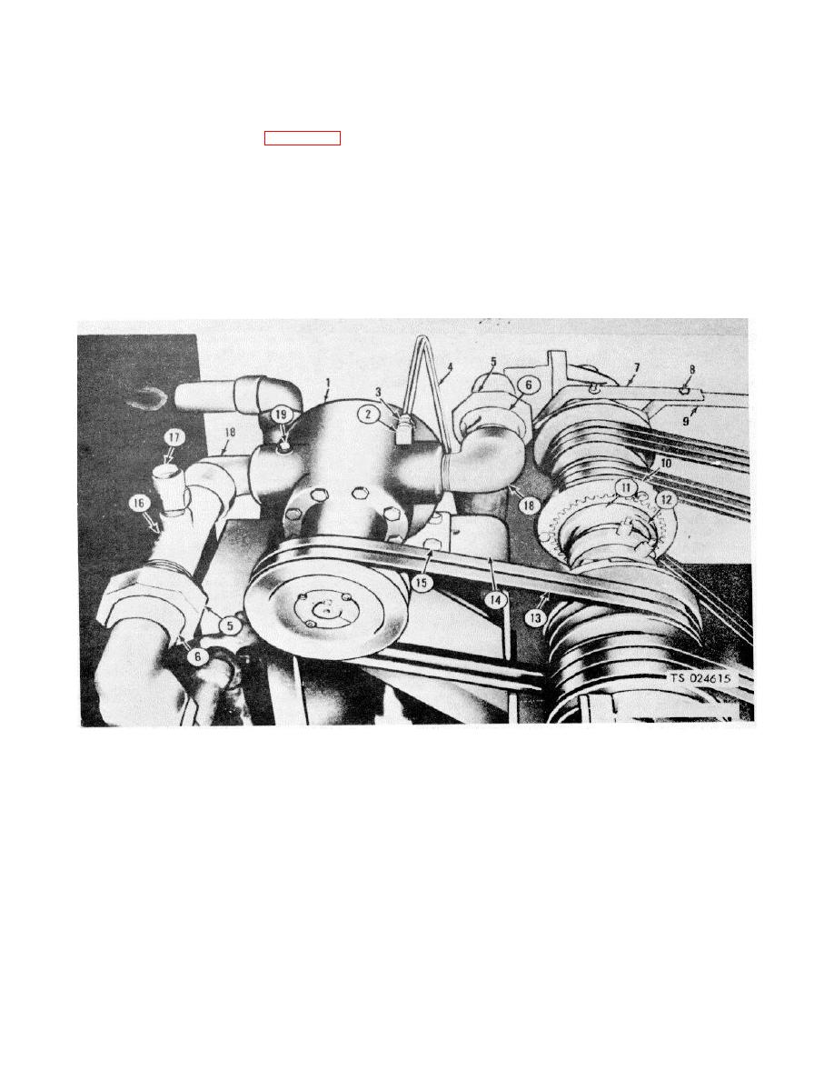
4-91. Clutch Adjustment
If the clutch shows a tendency to slip
a. Loosen the setscrew (11, fig. 4-88) in the
when load is applied, tighten adjusting
adjustment nut (12).
nut as above until there is no slippage.
b. Release the clutch as far as possible.
4-92. Drive Belts
c. Unscrew the adjusting nut(12) until the clutch
can easily be engaged.
a. General. Power is transmitted from the electric
d. Turn the adjusting nut (12) clockwise as far as
motor and gasoline engine by V-belts to line shafting,
possible by hand.
then from the shaft to the driven unit. Driven units are:
e. Release the clutch and tighten the adjusting nut
C02, transfer pump; refrigeration compressor; cylinder
1/8 turn.
filling compressor; generator.
f. Secure the adjusting screw in this position with
the setscrew (11).
1.
Transfer pump
8. Capscrew
2.
Adapter
9. Clutch arm
3.
Tube nut
10. Clutch drive ring
15.
Capscrew
4.
Tube
11. Setscrew
16.
Line assembly
5.
Union nut
12.. Adjusting nut
17.
Safety relief valve
6.
1/3 union
13. Drive belt
18.
Elbow
7.
Clutch arm
14. Frame
19.
Pipe plug
Figure 4-88. Clutch adjusting points.
4-99


