
TM 5-3655-210-12
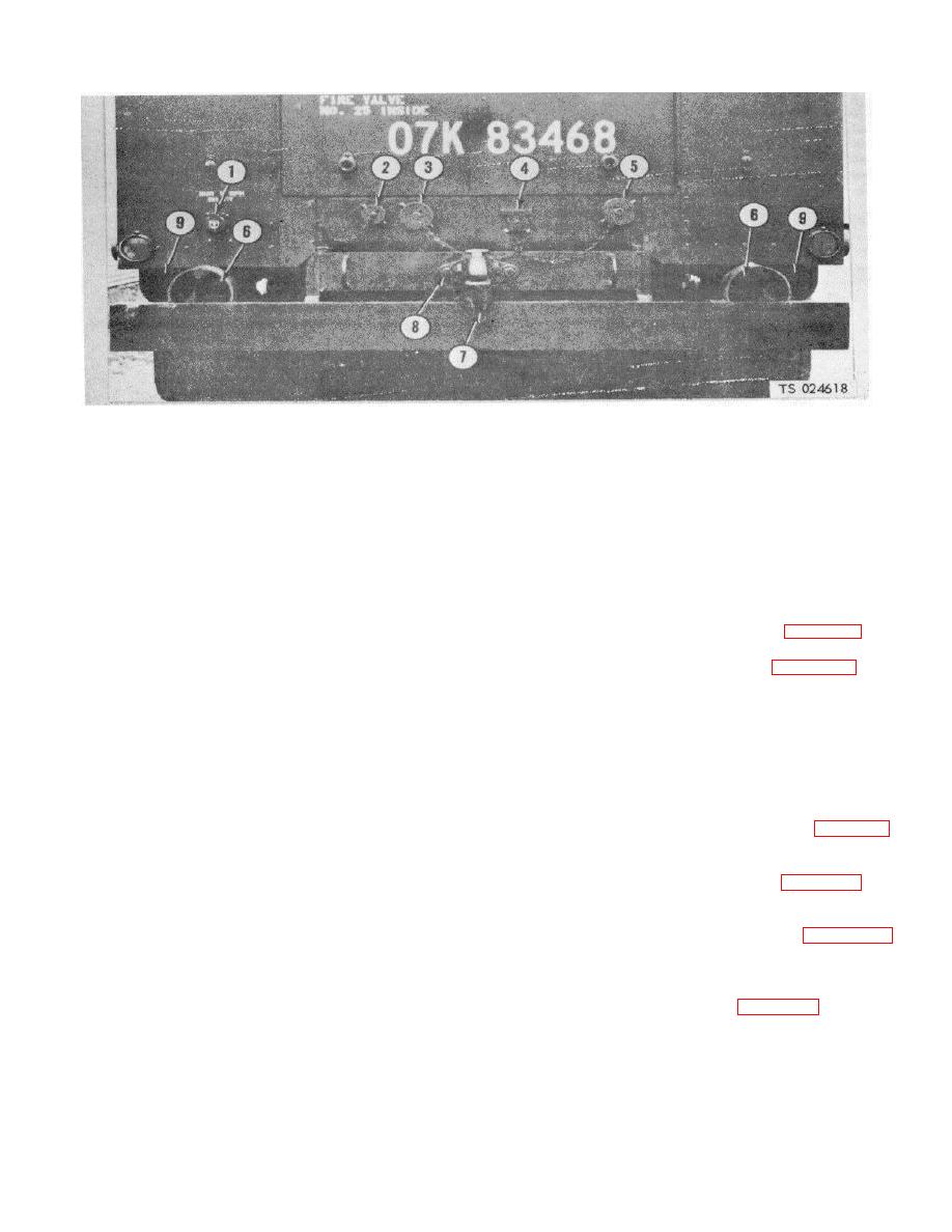
1.
208 v, ac power receptacle
6.
Blackout stop and taillight
2.
Vapor equalizing line
7.
Pintle hook
3.
Liquid fill line (pump by-pass)
8.
Capscrew
4.
24 v, dc receptacle
9.
Stop and taillight, service
5.
Liquid fill line
Figure 4-91. Power receptacles, installed view.
4-98. Cylinder Filling Manifold
(5) Unscrew the two union nuts (17), securing
the vapor manifold, and lift out the assembly.
a. Removal.
b. Disassembly.
Refer to figure 4-94 and
(1) Empty the pressure vessels.
disassemble the manifold.
(2) Remove the two unions (18, fig. 4-90) and
WARNING
nipples (17) from the manifold, at 3 and 5, figure 4-91.
(3) Loosen the hose nut(6, fig. 4-92) and
Dry cleaning solvent, P-D-680 or P-S-
remove the hose (5) from the valve (30).
661, used to clean parts is potentially
(4) Remove the two nuts (27) and U-bolt (29)
dangerous to personnel and property.
securing the pipe and valve (30) to the bracket (28).
Use in a well-ventilated area as the
(5) Loosen the tube nut securing the tube (22)
fumes are dangerous if inhaled. Avoid
to the valve assembly (25).
repeated and prolonged skin contact.
(6) Remove the four nuts (20) bevel washers
Do not use near open flame or
(21) and the two U-bolts (18) securing the cylinder filling
excessive heat. Flash point of solvent
manifold to the liquid manifold.
is 100F.-138F. (38C.-59C.).
(7) Loosen the five unions nuts (10, fig. 4-93),
c. Cleaning, Inspection and Repair. Wash all parts
securing the manifold to the piping and lift out the
in a cleaning solvent. Inspect the valves for loose nuts,
manifold assembly.
damaged threads, or any other damage. Tighten loose
(8) Remove the 1/3 union (13, fig. 4-94) and
nuts and replace damaged valves. Inspect for broken
nipple (12) from the vapor manifold connection at 2,
pipes and fittings or damaged threads. Replace broken
figure 4-91.
pipes and fittings.
(9) Remove the tube nut (14, fig.
d. Reassembly.
Refer to figure 4-94 and
securing the copper tube to the valve (15).
reassemble the manifold.
(10) Unscrew the two union nuts (17), securing
e. Installation. Reverse the procedure in a above.
the vapor manifold, and lift out the assembly.
(11) Remove the hose(3, fig. 4-95) from the
pipe (12) by unscrewing the hose nut (10).
4-103
