TM 5-3655-210-12
1.
Gage
8. Tube nut
15.
Cotter pin
22.
U-bolt
2.
Street elbow
9. Tube
16.
Cap
23.
Bracket
3.
Dampener
10. Cylinder filling valve
17.
Valve, pressure regulating
24.
Lockwasher
4.
Adapter bushing
11. Nut
18.
Adapter
25.
Nut
5.
Pipe
12. Lockwasher
19.
Washer
26.
Coupling
6.
Manifold assembly
13. U-bolt
20.
Frangible disc
27.
Screw
7.
Elbow
14. Chain
21.
Cap
28.
Handle
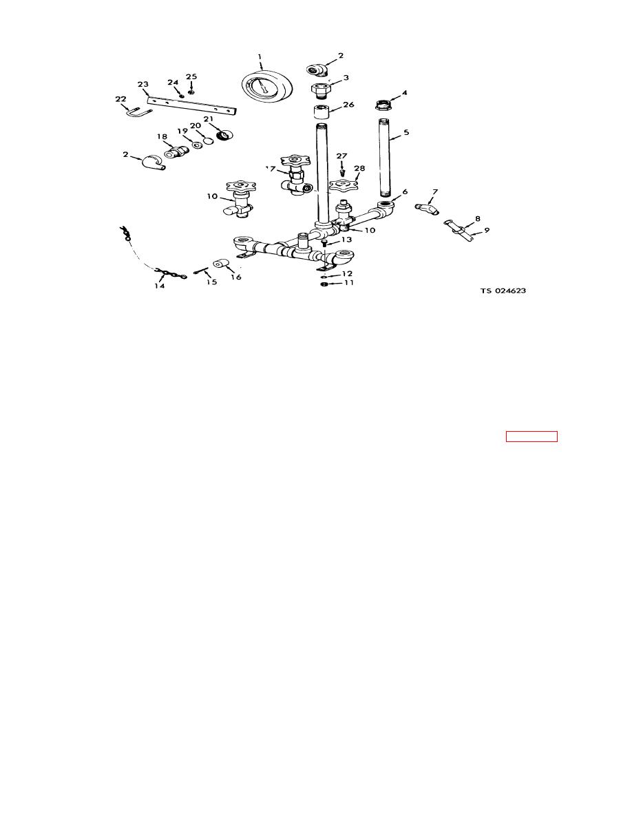
Figure 4-96. Cylinder filling manifold, exploded view.
(2) Loosen the tube nut (10, fig. 4-98) on the
b. Cleaning, Inspection and Repair. Clean the
gage to be adjusted, to relieve the pressure.
gage with a cloth dampened in a cleaning solvent.
(3) After waiting for several minutes for the
Wash all other parts in a cleaning solvent. Inspect for a
indicator to stabilize, tap the face of the gage slightly to
broken or damaged gage.
Replace if broken or
be sure the indicator is not sticking.
damaged. Inspect for damaged or cracked fittings and
(4) Turn the adjusting screw until the "zero"
damaged threads and replace all damaged parts.
mark is directly under the indicator.
c. Installation. Reverse the procedure in a. above.
(5) Tighten the tube nut.
d. Adjustment.
(6) Turn on the valves.
(1) Shutoff the valves (3,4,15 and 16, fig. 4-
Note
97).
The trailer must be level for the gages
to read correctly.
4-108


