TM 5-3655-210-12
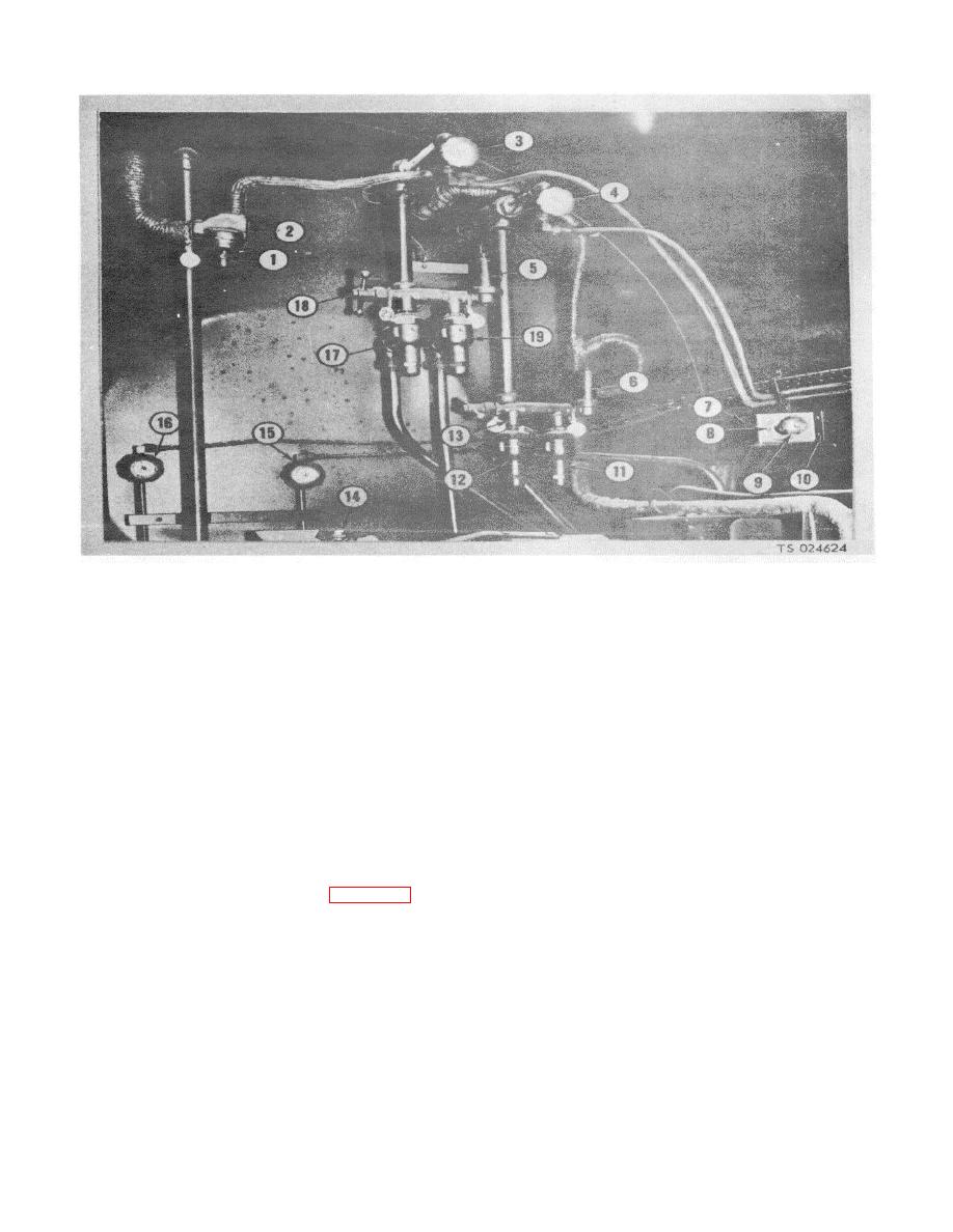
1. Expansion valve adjusting screw
2. Expansion valve
11.
Relief valve for carbon dioxide, storage
3. Low pressure gage line valve, conversion
12.
Relief valve for carbon dioxide, storage
4. Low pressure gage line valve, storage
13.
Safety vent switching valve, storage
5. Bleeder valve for carbon dioxide, conversion
14.
Safety relief valve, transfer pump
6. Bleeder valve for carbon dioxide, storage
15.
High pressure gage line, valve, conversion
7. Shutter control mounting bracket
16.
High pressure gage line valve, storage
8. Machine screw
17.
Relief valve for carbon dioxide, conversion
9. Shutter control
18.
Safety vent switching valve, conversion
10. Capscrew
19.
Relief valve for carbon dioxide, conversion
Figure 4-97. Power compartment valves and controls.
4-100. C02 Tank Pressure Gages
WARNING
Dry cleaning solvent, P-D-680 or P-S-
a. Removal.
661, used to clean parts is potentially
(1) Shut off the four valves (3, 4, 15 and 16,
dangerous
to
personnel
and
fig. 4-97).
property. Use in a well-ventilated
(2) Remove the hose nut (4, fig. 4-98) and
tube nut (10) securing the hose (3) and tube (11) to that
area as the fumes are dangerous if
gage.
inhaled.
Avoid repeated and
(3) Remove the elbow (5) and adapter (9) from
prolonged skin contact. Do not use
the tee.
near open flame or excessive heat.
(4) Remove the tee from the gage.
Flash point of solvent is 100F.-138F
(5) Remove the machine screws securing the
(38C.-59C.).
gage to the panel and remove the gage.
4-109


