TM 5-6640-212-14
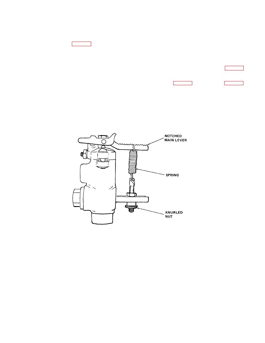
(6) To decrease differential between load and
CAUTION
unload move the spring away from the valve body.
Do not tamper with or change
Spring must be kept parallel to valve body.
exhaust port setting.
d. Discharge Valve. The discharge valve should be
(1)Tension of the spring (fig. 5-12) governs unload
removed, cleaned, and inspected after approximately
pressure within indicated range.
six months of operation.
Figure 5-13 shows an
(2)To increase unload pressure setting (within
exploded and cross-sectional view.
indicated range) tighten knurled nut after unlocking.
(1) Removal.
When desired pressure is attained, relock. Spring must
(a) Remove discharge valve cap (19, fig. 5-16)
be kept parallel to valve body.
and gasket (20).
(3)To decrease unload pressure setting (within
(b) Remove discharge valve plug (21) and lift out
indicated range), loosen knurled nut after unlocking, set
discharge valve (fig. 5-13) and gasket (29, fig. 5-16).
and relock. Spring must be kept parallel to valve body.
(2) Disassembly.
Refer to figure 5-13 and
(4)Position of the spring on notched main lever
disassemble the discharge valve.
governs the differential between load and unload
(3) Cleaning and Inspection.
pressure.
(a) Clean all parts thoroughly.
(5)To increase differential between load and unload,
(b) Inspect for damage or wear.
move the spring closer to the valve body.
(c) Replace damaged or worn parts.
Figure 5-12. Unloader Pilot Valve
5-23


