
TM 9-2510-247-13&P
0044 00
REMOVAL - Continued
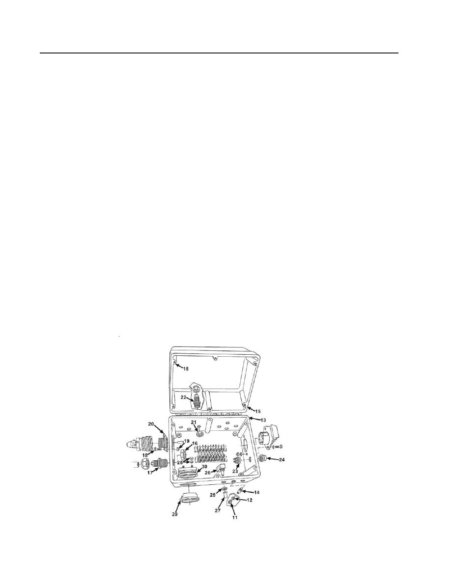
18. Loosen nut (23) from push switch (24) and remove push switch from control box.
19. Loosen three nuts (25) and remove three toggle switches (26) and rubber boots (27)
from electric control box.
20. Remove four nuts (28) from voltmeter (29) and remove cover (30) from back of voltmeter.
INSTALLATION
1.
Position voltmeter (29) on control box (13). Install cover (30) on voltmeter (29) and
secure with four nuts (28).
2.
Install rubber boots (27) on toggle switches (26).
3.
Position toggle switches (26) on control box and secure with nuts (25).
4.
Install push switch (24) on control box and secure with nut (23).
5.
Position seven straight adapters (22) on control box and secure with nuts (21).
6.
Position remote control receptacle (20) on control box and secure with four screws (18)
and new locknuts (19).
7.
Position bushing (17) on control box and secure with nut (16).
8.
Tighten six screws (15), securing lid to box.
9.
Install four threaded bolts (14) on bottom of electrical control box (13).
10. Position electrical control box on fender and secure with four new lockwashers (12) and nuts (11).
Figure 79. Electrical Control Box
0044 00-4
