TM 9-2510-247-13&P
0045 00
REMOVAL - Continued
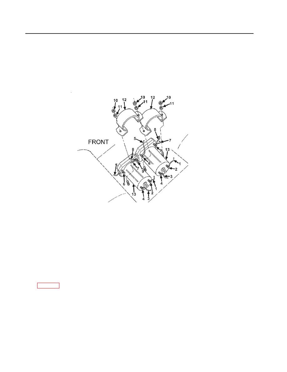
3. Disconnect ground wire (5) from terminal post (6).
4. Disconnect solenoid to control box wire (7) and jumper wire (8) from terminal post (9).
5. Remove nuts (10) and lockwashers (11). Discard lockwashers.
6. Remove mounting bracket (12) from solenoid (13).
7. Remove solenoid (13).
Figure 81. Solenoid Assembly
INSTALLATION
1. Position solenoid (13) and secure with mounting bracket (12), nuts (10), and new
lockwashers (11).
2. Connect solenoid to control box wire (7) and jumper wire (8) to terminal post (9).
3. Connect ground wire (5) to terminal post (6).
4. Connect solenoid to battery wire (3) to terminal post (4).
5. Connect solenoid to hydraulic motor wire (1) to terminal post (2). Connect batteries
6. Turn ELECTRICAL switch to ON. Push motor control button for 2 seconds and release to
ensure the solenoids activate the hydraulic motors.
Follow-on Tasks:
None
END OF WORK PACKAGE
0045 00-2


