
TM 9-2510-247-13&P
0044 00
INSTALLATION - Continued
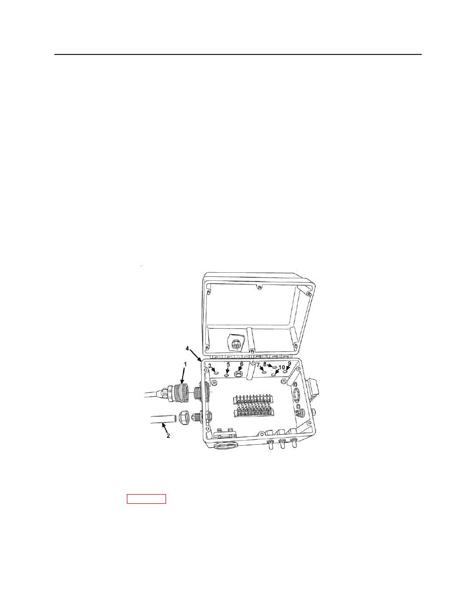
11. Connect blackout control cable (10).
12. Connect worklight cable (9).
13. Connect hydraulic solenoid valve cable (8).
14. Connect strobe light wires (7).
15. Connect electrical control box to solenoid cable (6).
16. Connect electrical control box to battery cable (5).
17. Connect ground cable (3) to control box (4).
18. Connect junction box to electrical control box harness (2).
19. Connect remote control harness (1).
NOTE
ALL CABLES/WIRING REMOVED FOR CLARITY.
Figure 78. Electrical Control Box
Follow-on Tasks:
Connect batteries (WP 0050).
Check for proper operation of electrical control box.
END OF WORK PACKAGE
0044 00-5
