TM 9-2510-247-13&P
0060 00
INSTALLATION
NOTE
Handles can only be replaced from right to left.
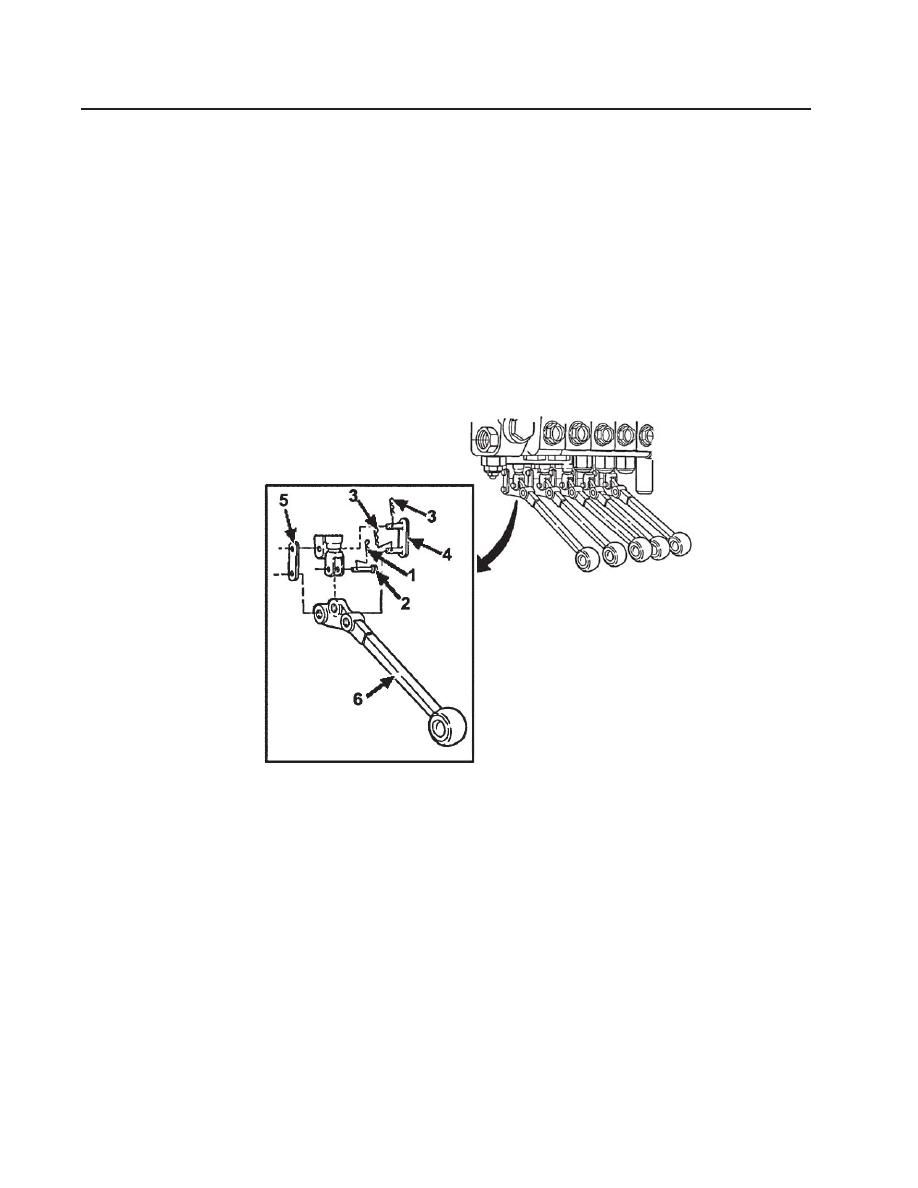
1. Install control lever (6).
2. Install connecting links (4) and (5) and retaining pins (3).
3. Install retaining pin (1) and pin (2).
Figure 109. Hydraulic Control Lever
Follow-on Maintenance:
Check for proper operation
END OF WORK PACKAGE
0060 00-2


