TM 9--2520--215--34
0040 00--1
OUTPUT REDUCTION GEAR BRAKE APPLY REACTION PLATE
REPLACEMENT
0040 00
THIS WORK PACKAGE COVERS:
Removal, Installation
INITIAL SETUP:
Tools and Special Tools
General mechanic’s tool kit (item 1, WP 0088 00)
Lifting sling (item 18, WP 0088 00)
Suitable lifting device (2000 lb capacity min)
Fabricated stand (figure 2, WP 0089 00)
Materials/Parts
Self--locking bolts (2) (item 106, WP 0087 00)
Self--locking bolts (27) (item 105, WP 0087 00)
Equipment Conditions
Output reduction gear assembly removed
(TM 9--2350--292--20 or TM 9--2350--256--20)
REMOVAL
NOTE
Output reduction gear assemblies of the XT--1410--5A do not contain studs for mounting the
sprockets.
Disassembly procedures for the right and left output reduction gear assemblies are identical.
Only the left assembly is illustrated.
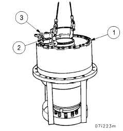
1. Using a suitable lifting device and lifting sling, position output reduction gear assembly in fabricated stand. Do not
remove sling. Remove all self--locking bolts (1) except those under lever (2) and those retaining stop (3). Discard
self--locking bolts.