TM 9--2520--215--34
0041 00--2
BRAKE APPLY REACTION PLATES AND RELATED PARTS REPAIR –
CONTINUED
0041 00
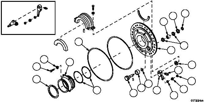
DISASSEMBLY – Continued
1. Remove snap ring (1) and spacer (2) from brake drum shaft (3). Tap brake apply shaft (3) out of assembly.
Discard snap ring.
NOTE
On the left assembly, air valve actuating lever is used instead of spacer.
2. Remove brake apply lever (4) and spacer (5).
3. Remove lubrication fitting (6), two seals (7) and needle bearing (8). Two seals (7) may be removed with hook tool
or pressed with bearing. Discard seals.
4. Remove bearing (9), preformed packing (10) and two seals (11) from saddle (12). Remove seal and preformed
packing with hooked tool. Remove bearing by pressing out. Discard preformed packing, seals and bearing.
5. Remove needle--bearing (13) by inserting drift behind bearing and tap out.
6. Remove hook--type seal ring (14) from saddle sleeve (15). Discard seal ring.
7. Remove six screws (16) and six lockwashers (17). Discard lockwashers.
8. Remove saddle sleeve (15) out of saddle (12). Remove two preformed packings (18) from saddle sleeve (15).
Discard preformed packings.
9. Remove preformed packing (19) from outer groove of saddle (12). Discard preformed packing.
1
2
9
11
12
5
7
8
7
10
13
3
18
14
16
17
19
4
6
LEFT SIDE ONLY
15